
產品介紹
首頁 > 產品介紹 > 量測儀器 > 晶體曲線分析儀
晶體曲線分析儀


功能說明
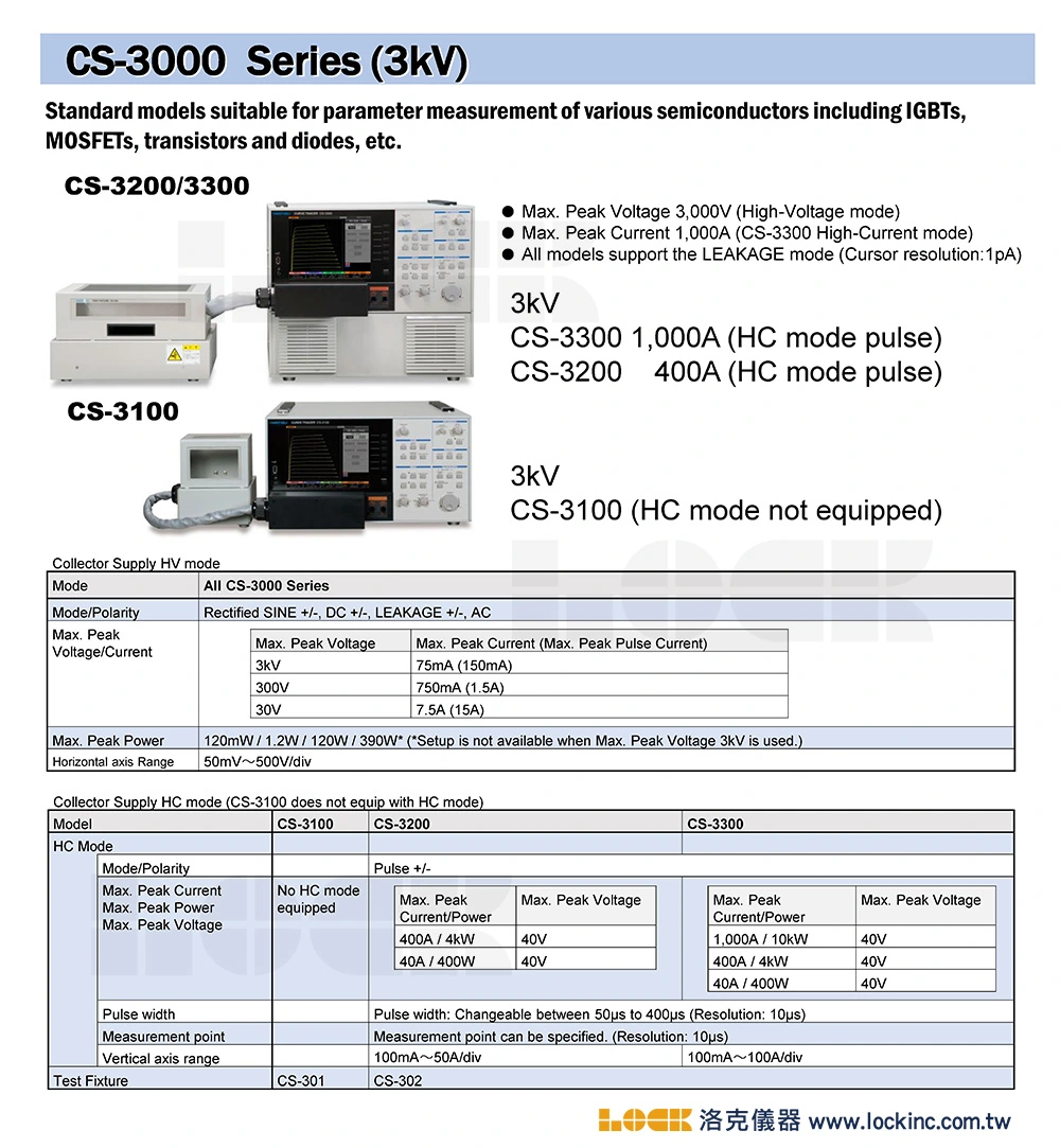
- Maximum peak voltage: 3,000 V (high-voltage mode for all models)
- Maximum peak current: 1,000 A (CS-3300 High-current mode)
- All models support the Leakage mode (cursor resolution: 1 pA)
- USB for Screen copy and saving setups
- LAN Interface for remote control
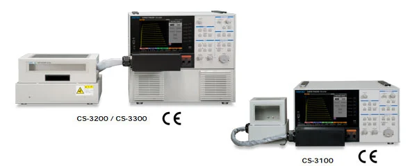
Lineup
|
User-friendly m
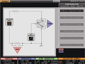 |
| Graphical configuration selection |
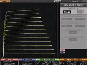 |
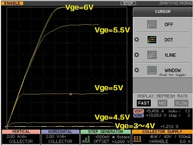
| Transistor I-V characteristic example (Trace mode) |
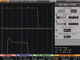 |
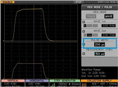
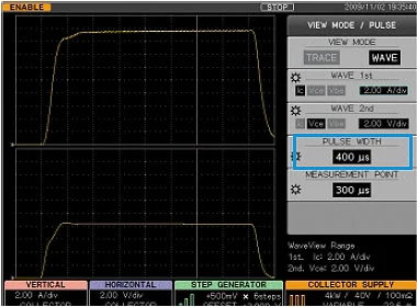
| Vbe and Ic waveforms in the high current pulse mode (Wave mode) |
easurement screen
| Item | CS-3100 | CS-3200 | CS-3300 | |||
| • Collector supply | ||||||
| Mode | High voltage | AC, ± Rectified SIN, ± DC, ± LEAKAGE | ||||
| Large current | - | Pulse only | ||||
| Maximum peak power | 120 mW, 1.2 W, 12 W, 120 W, 390 W *390 W can be selected excluding the maximum peak voltage setting at 3,000 V range. |
|||||
| - | Large current mode ( 400 W, 4 kW ) |
Large current mode ( 400 W, 4 kW, 10 kW ) |
||||
| High voltage mode | 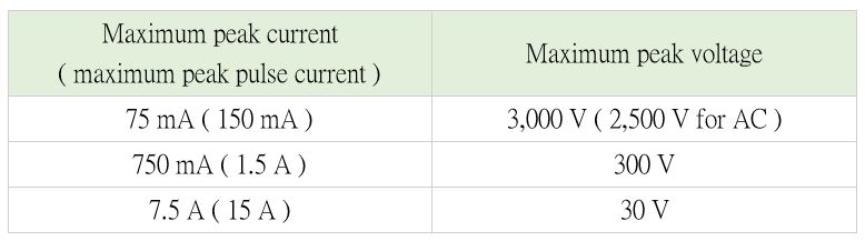 |
|||||
| Loop correction | The stray capacitance between the collector terminal and the ground of the fixture is compensated by the hardware in the high voltage mode. Digital compensation is also available. | |||||
| Loop corrent mode ( pulse only ) |
 |
 |
||||
| Pulse width / measurement point | - | The pulse width is variable in the range from 50 µs to 400 µs. Measurement points can be specified ( with a resolution of 10 µs/step ). |
||||
| Maximum number of data points | 20 to 1,000 point can be specified per trace. | |||||
| • Step generator | ||||||
| Current mode | Amplitude range : 50 nA, 21 ranges, at 1-2-5 step Maximum current : ± 2A / Offset : ± 10 times STEP AMPLITUDE setting |
|||||
| Voltage mode | Amplitude range : 50 mV to 2 V, 6 ranges, at 1-2-5 step Maximum voltage : ± 40V / Offset ± 10 times STEP AMPLITUDE setting |
|||||
| Step rate | Staircase wave : 2 times of 50 Hz or 60 Hz ( 50 Hz or 60 Hz in the AC mode ) |
Staircase wave : 2 times of 50 Hz or 60 Hz ( 50 Hz or 60 Hz in the AC mode ) Pulse : The pulse changes in the range from 80ms, to 1,000 ms. ( The lowest frequency limited by the maximum peak power consumption setting. ) |
||||
| Pulse step | The pulse width is yariable in the range from 50 µs to 400 µs at 10 µs resolution. | |||||
| Number of steps | 0 to 20 steps | |||||
| • AUX output | ||||||
| Range | OFF, -40 V to +40 V, varisble with at 100mV resolution | |||||
| • Vertical axis | ||||||
| Collector voltage | Range | High voltage mode : 1 µA / div to 2 A / div, 20 ranges, at 1-2-5 step. | ||||
| High current mode : 100 mA / div to 50 A / div, 9 renges, at 1-2-5 step. | High current mode : 100 mA / div to 100 A / div, 10 renges, at 1-2-5 step. | |||||
| Accuracy | 2% of readout + 0.05 x VERT / div setting value or lower ( The internal loop correction error below must be added to the left formula. ) 3 kV range : 6 µA, 300 V range : 1 µA, 30 V range : 0.5 µA ( Defined only for the area of 10% or more of each voltage range. ) |
|||||
| Emitter current (LEAKAGE) |
Range | 1 nA / div - 2 mA / div, 20 ranges, at 1-2-5 step | ||||
| Accuracy | 2% of readout + 0.05 x VERT / div setting + 1 nA or lower | |||||
| • Horizontal axis | ||||||
| Collector voltage |
Range | High voltage mode : 50 mV / div to 500 V / div, 13 ranges, at 1-2-5 step | ||||
| - | High current mode : 50 mV / div to 5 V / div, 7 ranges, at 1-2-5 switching |
|||||
| Accuracy | 2% of readout + 0.05 x HORIZ / div setting or better | |||||
| Base / emitter voltage | Range | 50 mV / div to 5 V /div, 7 ranges, at 1-2-5 step | ||||
| Accuracy | 2% of readout + 0.05 x HORIZ / div setting + 1 nA or lower | |||||
| • Miscellaneous | ||||||
| Monitor | 8.4-inch color TFT-LCD ( SVGA 800 x 600 pixels ) | |||||
| Data saving / reading | Intemal : Memory ( setup : 256, REF waveform : 4 ) External : Removable storage connected to the USB port ( setup, waveform saving / recall, screen hard copy ) |
|||||
| USB | 1 port ( USB 1.1 ) | |||||
| Remote control | Remote control by LAN : 1 port ( 100BASE-TX ) | |||||
| Power supply / power consumption | Power supply input range : 100 to 240 V AC, 50 / 60 Hz Power consumption : 500 VA |
|||||
| Accessories | CS-301 ( fixture S ), CS-500 ( test adapter ), operation manual, power cord |
CS-302 ( fixture M ),CS-500 ( test adapter ), wire set,operation manual,power cord |
||||
| • Mechanism section | ||||||
| Dimensions ( mm ) | 424 (W) x 555.2 (L) x 221 (H) ( without the external projection portion ) |
424 (W) x 555.2 (L) x 354.5 (H) ( without the external projection portion ) |
||||
| Weight | Approx. 30 kg ( without optional accessories ) |
Approx. 45 kg ( without optional accessories ) | ||||
| Environmental conditions | Operating temperature : 0 to +40 °C, performance guarantee temperature : +10 to +35 °C |
|||||
Observation of I-V curves as well as applied waveforms of voltage and current
Application of the current and voltage pulses in the high current mode
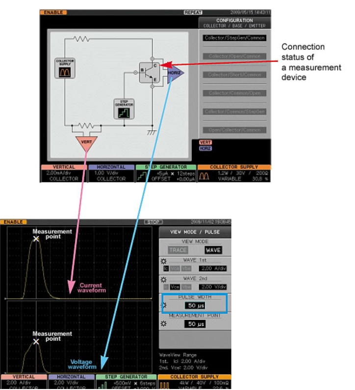 |
|
| The pulse widths of the applied current and voltage and the measurement point can be specified in the range from 50 to 400 μs (CS-3200 and CS-3300). | |
 |
|
 |
|
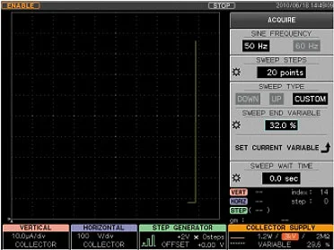
Example of measuring MOSFET “current vs. voltage” characteristics
 |
SWEEP TYPE can be selected
| SWEEP TYPE can be selected from DOWN, UP, and CUSTOM (all models). With CUSTOM specified, the range between specified values can be swept. |
規格說明
| Collector Supply HV mode | ||||
| Mode | All CS - 3000 Series | |||
| Mode / Polarity | Rectified SINE +/- , DC +/- , LEAKAGE +/- , AC | |||
| Max. Peak Voltage / Current |
Max. Peak Voltage | Max.Peak Current ( Max. Peak Pulse Current ) | ||
| 3 kV | 75 mA ( 150 mA ) | |||
| 300 V | 750 mA ( 1.5 A ) | |||
| 30 V | 7.5 A ( 15A ) | |||
| Max. Peak Power | 120 mW / 1.2 W / 120 W / 390 W* ( *Setup is not available when Max. Peak Voltage 3 kV is used. ) | |||
| 10.00000 V | 50 mV ~ 500 V / div | |||
| Collector Supply HV mode | ||||||
| Mode | CS - 3100 | CS - 3200 | CS - 3300 | |||
| HC Mode | Mode / Polarity | Pulse +/- | ||||
| Max. Peak Current Max. Peak Power Max. Peak Voltage |
No HC mode exquipped |
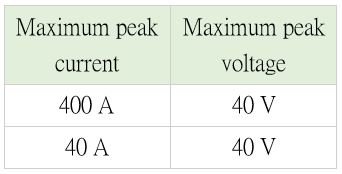
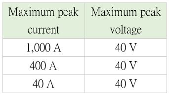
Max. Peak Current/Power |
Max. Peak Voltage | Max. Peak Current/Power | Max. Peak Voltage | |
| 400 A / 4 kW | 40 V | 1000 A / 10 kW | 40 V | |||
| 40 A / 400 W | 40 V | 400 A / 4 kW | 40 V | |||
| 40 A / 400 W | 40 V | |||||
| Pulse width | Pulse width : Changeable between 50 µs to 400 µs ( Resolution : 10 µs ) | |||||
| Measurement point | Measurement point can be specified. ( Resolution : 10 µs ) | |||||
| Vertical axis range | 100 mA ~ 50 A / div | 100 mA ~ 100 A / div | ||||
| Test Fixture | CS - 301 | CS - 302 | ||||