U6200A
Picotest 12位數/秒通用計頻器
產品說明


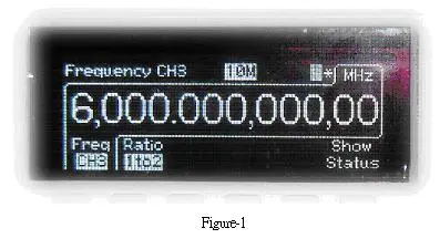
本公司根據ISO9004製程所生產出的U6200A萬用計頻器能夠提供每秒12位數頻率解析(見Figure-1)、40 ps時間間隔解析,以及完整的測試與分析功能。另外,本產品還內建第三頻道,可量測頻率從375 MHz到6GHz,而第一和第二頻道,可量測頻率從1 mHz到 to 400 MHz。
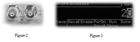
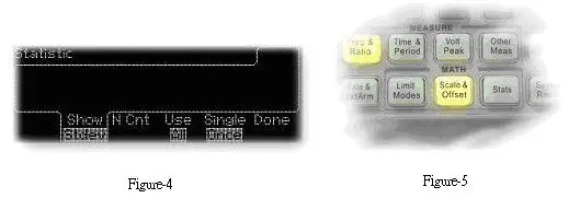
本產品U6200A也提供了其它不錯的功能及設計,例如:頻率比率(每秒11位)、時間間隔、週期(2.5 ns至1000 s)、 工作週期、脈衝寬度、上升/下降時間、峰值電壓(100 Hz到300 MHz)、相位、總計、時基溫度變化穩定度 (小於 1 PPM)、老化率(每年小於 2 PPM)、時基參考(I/O見Figure-2)、前端完全隔離。另外還提供20組記憶空間,讓使用者儲存常用的設定(見Figure-3)。
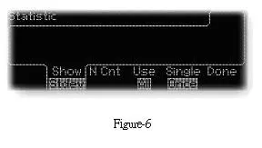
本產品U6200A內建統計及數學運算功能。使用者可以做一般量測、同步量測、中間值統計、最大/最小值統計、三角函數統計及標準差統計(見Figure-4)。以及運用Scale & Offset功能按鍵,使用者可依實際應用加入補償值。而要完成以上操作並依需求輸入數值,使用者只要輕易地利用本產品面板上的數字鍵即可。再者,本公司為了使用者操作方便,將功能按鍵設計成當功能啟用時,按鍵便會亮起(見Figure-5)。
本產品U6200A採用即時數位訊號進程技術,即可在分析數據之際,同時讀取新值並做快速量測。值得一提的是「限制模式」,使用者可以依需求設定最大及最小界值,並透過面板設定成Go-On或Stop,再開啟USB Output,此時只要量測值超過所設定的範圍,U6200A就會依設定繼續或停止量測,同時送出訊號觸發外部裝置(見Figure-6)。
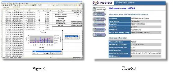
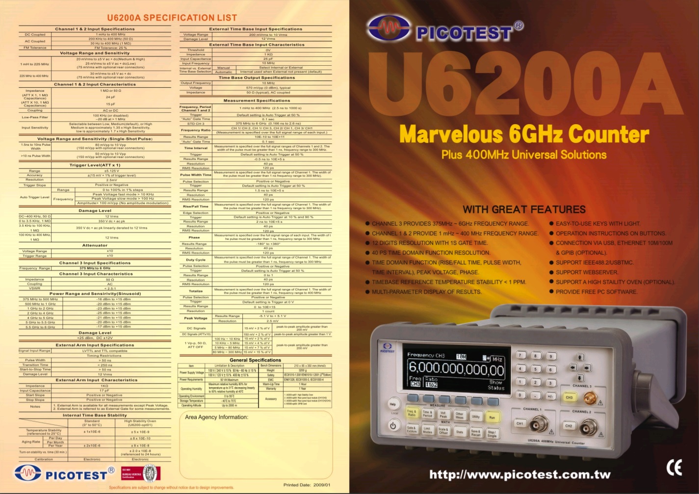
使用者除了可以透過微軟Excel應用軟體,經由內建的USB或選購的GPIB介面取得資料,還可以利用U6200A支援網路伺服器功能,將內建的乙太網路連結PC,並在PC上的網路瀏覽器中鍵入預設的位址192.168.0.247,使用者便可透過圖像使用者介面GUI操控U6200A。另外,靠著與安捷倫53132A相容的SCPI指令集,U6200A能夠在應用上提供使用者熟悉的語法字串。
| Channel 1 & 2 ( for U6200A only ) Input Specifications | |
| DC Coupled | 1 MHz to 400 MHz |
| AC Coupled | 200 KHz to 400 MHz ( 50 Ω ) 30 Hz to 400 MHz ( 1 MΩ ) |
| FM Tolerance | FM Tolerance : 25% |
| Voltage Range and Sensitivity | |
| 1 mH to 225 MHz | 20 mVrms to ±5 V ac + dc ( Medium and High ) 25 mVrms to ±5 V ac + dc ( Low ) |
| 225 MHz to 400 MHz | 30 mVrms to ±5 V ac + dc |
| Channel 1 & 2 ( for U6200A only ) Input Characteristics | |
| Impedance ( ATT X 1, 1 MΩ Capacitance ) ( ATT X 10, 1 MΩ Capacitance ) |
1 MΩ or 50 MΩ 24 pF 15pF |
| Coupling | AC or DC |
| Low - Pass Filter | 100 KHz ( or disabled ) -20 dB at > 1 MHz |
| Input Sensitivity | Selectable between Low, Medium ( default ), or High Medium is approximately 1.35x High Sensitivity, low is approximately 1.7x High Sensitivity |
| Internal Noise | 200 uVrms ( typical ) |
| Voltage Range and Sensitivity ( Single - Shot Pulse ) | |
| 1.5 ns to 10 ns Pulse Width | 80 mVpp to 10 Vpp ( 150 mVpp with optional rear connectors ) |
| > 10 ns Pulse Width | 50 mVpp to 10 Vpp ( 150 mVpp with optional rear connectors ) |
| Trigger Level ( ATT x 1 ) | ||
| Range | ±5.125 V | |
| Accuracy | ±( 15 mV + 1% of trigger level ) | |
| Resolution | 2.5 mV | |
| ATT x 10 Range | X 10 | |
| Trigger Slope | Positive or Negative | |
| Auto Trigger Level | Range | 0 to 100% in 1% steps |
| Frequency | Peak Voltage fast mode > 10 KHz Peak Voltage slow mode > 100 Hz Amplitude > 100 mVpp ( No amplitude modulation ) |
|
| Damage Level | |
| DC ~ 400 MHz 50 Ω | 12 Vrms |
| 0 to 3.5 KHz, 1 MΩ | 350 V dc + ac pk |
| 3.5 KHz to 100 KHz, 1 MΩ | 350 V dc + ac pk linearly derated to 12 Vrms |
| 100 KHz to 400 MHz, 1 MΩ | 12 Vrms |
| Attenuator | |
| Voltage Range | x10 |
| Trigger Range | x10 |
| Channel 3 Input Specifications ( for U6200A only ) | ||
| Frequency Range | 375 MHz to 6 GHz | |
| Channel 3 Input Characteristics ( for U6200A only ) | ||
| Impedance | 50Ω | |
| Couping | AC | |
| VSWR | < 2.5 : 1 | |
| Power Range and Sensitivity ( Sinusoid ) | ||
| 375 MHz to 500 MHz | -16 dBm to + 15 dBm | |
| 500 MHz to 1 GHz | -20 dBm to + 15 dBm | |
| 1 GHz to 2 GHz | -23 dBm to + 15 dBm | |
| 2 GHz to 4 GHz | -25 dBm to + 15 dBm | |
| 4 GHz to 5 GHz | -21 dBm to + 15 dBm | |
| 5 GHz to 5.5 GHz | -20 dBm to + 15 dBm | |
| 5.5 GHz to 6 GHz | -17 dBm to + 15 dBm | |
| Damage Level | ||
| +25 dBm, DC ±12V | ||
| External Arm Input Specifications | |
| Signal Input Range | LVTTL and TTL compatible |
| Timing Restrictions | |
| Pulse Width | > 50 ns |
| Transition Time | < 250 ns |
| Start - to - Stop Time | > 50 ns |
| Damage Level | 12 Vrms |
| External Arm Input Characteristics | |
| Impedance | 1 kΩ |
| Input Capacitance | 17 pF |
| Start Slope | Positive or Negative |
| Stop Slope | Positive or Negative |
| Notes | 1. External Arm is available for all measurements except Peak Volts. 2. External Arm is referred to as External Gate for some measurement. |
| Internal Time Base Stability | ||
| Standard ( 0° to 50°C ) | ||
| Temperature Stability ( referenced to 25°C ) |
< ± 1 x 10⁻⁶ | |
| Aging Rate | Per Day Per Month Per Year |
< ± 0.2 x 10⁻⁶ ± 2 ppm |
| Calibration | Electronic | |
| External Time Base Input Specifications | ||
| Voltage Range | 200 mVrms to 10 Vrms | |
| Damage Level | 12 Vrms | |
| External Time Base Input Characteristics | ||
| Threshold | 0 V | |
| Impedance | 1 kΩ | |
| Input Capacitace | 25 pF | |
| Input Frequency | 10 MHz | |
| Internal vs. External Time Base Selection | Manual | Select Internal or External |
| Automatic | Internal used when External not persent ( default ) |
|
| Time Base Output Specifications | ||
| Output Frequency | 10 MHz | |
| Voltage | 570 mVpp ( 0 dBm ), typical | |
| Impedance | 50 Ω (typical), AC coupled | |
| Measurement Specifications | ||||
| Frequency, Period Channel 1 and 2 | 1 mHz to 400 MHz ( 2.5 ns to 1000 s ) | |||
| Trigger | Default setting is Auto Trigger at 50% | |||
| " Default " Gate Time | 0.1 sec | |||
| STD CH 3 | 375 MHz to 6 GHz ( 0.166 ns to 2.6 ns ) | |||
| Frequency Ratio | CH 1 / CH 2, CH 1 / CH 3, CH 2 / CH 1, CH 3 / CH1 | |||
| ( Measurement is specified over the full signal range of each input. ) |
||||
| Results Range | 10-10 to 1011 | |||
| " Default " Gate Time | 0.1 sec | |||
| Time Interval | Measurement is specified over the full signal range of Channels 1 and 2. The width of the pulse must be greater than 1 ns, frequency range to 300 MHz. | |||
| Trigger | Default setting is Auto Trigger at 50% | |||
| Results Range | -0.5 ns to 105s | |||
| Resolution | 40 ps | |||
| RMS Resolution | 120 ps | |||
| Systematic Uncertainty | ± ( TI x Time Base Error ) ± Trigger Level Timing Error ± 500 ps Differential Channel Error |
|||
| Pulse Width Time | Measurement is specified over the full signal range of Channel 1. The width of the pulse must be greater than 1 ns frequency range to 300 MHz ). | |||
| Pulse Selection | Positive or Negative | |||
| Trigger | Default setting is Auto Trigger at 50% | |||
| Results Range | 1.5 ns to 105 s | |||
| Resolution | 40 ps | |||
| RMS Resolution | 120 ps | |||
| Systematic Uncertainty | ± ( Pulse Width Time x Time Base Error ) ± Trigger Level Timing Error ± 500 ps Differential Channel Error. | |||
| Rise / Fall Time | Measurement is specified over the full signal range of Channel 1. The width of the pulse must be greater than 1 ns frequency range to 300 MHz ). | |||
| Edge Selection | Positive or Negative | |||
| Trigger | Default setting is Auto Trigger at 10% and 90% | |||
| Results Range | 2 ns to 105 s | |||
| Resolution | 40 ps | |||
| RMS Resolution | 120 ps | |||
| Systematic Uncertainty | ± ( Edge Time x Time Base Error ) ± Trigger Level Timing Error ± 500 ps Differential Channel Error | |||
| Phase | Measurement is specified over the full signal range of each input. The width of the pulse must be greater than 1 ns, frequency range to 300 MHz | |||
| Results Range | -180° to +360° | |||
| Resolution | 40 ps | |||
| RMS Resolution | 120 ps | |||
| Systematic Uncertainty | ± ( Trigger Level Timing Error ) x Frequency | |||
| Duty Cycle | Measurement is specified over the full signal range of Channel 1. The width of the pulse must be greater than 1 ns, frequency range to 300 MHz | |||
| Pulse Selection | Positive or Negative | |||
| Trigger | Default setting is Auto Trigger at 50% | |||
| Results Range | 0 to 1 | |||
| Resolution | 40 ps | |||
| RMS Resolution | 120 ps | |||
| SystematicUncertainty | ± Trigger Level Timing Error ± 500 ps Differential Channel Error |
|||
| Totalize | Measurement is spcified over the full signal range of Channel 1. The width of the pulse must be greater than 1 ns, frequency range to 400 MHz | |||
| Pulse Selection | Positive or Negative | |||
| Trigger | Default setting is Trigger at 0 V | |||
| Results Range | 0 to 1015 | |||
| Resolution | 1 count | |||
| Systematic Uncertainty | ± 1 count | |||
| Peak Voltage | Results Range | -5.1 V to + 5.1 V | ||
| Resolution | 2.5 mV | |||
| DC Signals | 15 mV + 2% of V | peak-to-peak amplitude greater than 200 mV | ||
| DC Signals | 15 mV + 2% of V | peak-to-peak amplitude greater than 1 V | ||
| 1 Vp-p, 50Ω, ATT OFF | 10 Hz ~10 KHz | 15 mV + 2% of V | peak-to-peak amplitude greater than 200 mV | |
| 10 KHz ~ 5 MHz | 15 mV + 4% of V | |||
| 5 MHz ~ 80 MHz | 15 mV + 7% of V | |||
| 80 MHz ~ 300 MHz | 15 mV + 15% of V | |||
| Rear Input Option Channel Isolation | ||
| Frequency | Front Channel ( dB ) |
Rear Channel ( dB ) |
| 100 KHz | < -85 | < -85 |
| 1 MHz | -85 | -75 |
| 10 MHz | -78 | -55 |
| 50 MHz | -67 | -42 |
| 100 MHz | -62 | -37 |
| 200 MHz | -55 | -35 |
| 300 MHz | -50 | -36 |
| 400 MHz | -47 | -33 |
| Rms | 100 Hz | 1 KHz | 10 KHz | 100 KHz |
| U62 ( 10ms ) |
0.000000842 | 0.000003438 | 0.000013896 | 0.000067275 |
| U62 ( 100ms ) |
0.0000001 | 0.000000828 | 0.000005093 | 0.000011508 |
| U62 ( 1s ) |
0.000000001 | 0.000000098 | 0.000001212 | 0.000004869 |
| Rms | 1 MHz | 10 MHz | 100 MHz | 1 GHz |
| U62 ( 10ms ) |
0.000677504 | 0.0048303870 | 0.072107484 | 0.611551072 |
| U62 ( 100ms ) |
0.000101040 | 0.002272900 | 0.006344503 | 0.055991810 |
| U62 ( 1s ) |
0.000058166 | 0.000469601 | 0.001275299 | 0.002602258 |


 '
'※ Note : The U6220A doesn't provide the function via the channel 2 colored green.
| Value at *RST ( GPIB Reset ) |
In Save / Recal |
In non - volatile memory |
||
| Input impedance |
CH1 | 1E + 6Ohms | YES | NO |
| CH2 | 1E + 6Ohms | YES | NO | |
| Input Attenuation |
CH1 | x 1 | YES | NO |
| CH2 | x 1 | YES | NO | |
| Trigger Level |
CH1 ( percent ) | 50 | YES | NO |
| CH2 ( percent ) | 50 | YES | NO | |
| CH1 ( volts ) | 0 | YES | NO | |
| CH2 ( volts ) | 0 | YES | NO | |
| Trigger Slope |
CH1 | positive | YES | NO |
| CH2 | positive | YES | NO | |
| Sensitivity | CH1 | Medium | YES | NO |
| CH2 | Medium | YES | NO | |
| Scale | 1 | YES | NO | |
| Offset | 0 | YES | NO | |
| Limits parameters |
Limit test on / off | off | YES | NO |
| On fail stop / go on | go on | YES | NO | |
| Lower limit | 0 | YES | NO | |
| Upper Limit | 0 | YES | NO | |
| Stats parameters |
Stats on / off | off | YES | NO |
| Measurement count |
100 | YES | NO | |
| Display measurement / stats |
measurement | YES | NO | |
| Use all / in limlts | all | YES | NO | |
| On - single measurement |
1 | YES | NO | |
| Timebase | auto | YES | NO | |
| Trigger Offset Cal Parameters |
Channel 1 trigger offset Inp1 cal | NO | YES | |
| Channel 2 trigger offset Inp2 cal |
NO | YES | ||
| Channel 1 trigger offset Att1 cal |
NO | YES | ||
| Channel 2 trigger offset Att2 cal |
NO | YES | ||
| Trigger Gain Cal Parameters |
Channel 1 trigger gain Inp1 cal |
NO | YES | |
| Channel 2 trigger gain Inp2 cal |
NO | YES | ||
| Channel 1 trigger gain Att1 cal |
NO | YES | ||
| Channel 2 trigger gain Att2 cal |
NO | YES | ||
| Time Interval Offset Cal Parameters |
Fine 1 | NO | YES | |
| Fine 2 | NO | YES | ||
| Quick | NO | YES | ||
| Timebase cal Parameters | NO | YES | ||
※ Note : The U6220A doesn't support the accessories from item 1 ~ 4 colored green.
| Item | Limitation & description |
| Power Supply Voltage | 100V / 240V ± 10% 50Hz ~ 60Hz ± 10% |
| 100V / 120V ± 10% 400Hz ± 10% | |
| Power Requirements | Max. 80VA ( 30W Typtical ) |
| Operating Humidity | Maximum relative humidity 80% for temperature up to 31 °C decreasing linearly to 50% relative humidity at 40 °C |
| Operating Environment | 0 to 55 °C |
| Storage Temperature | -40 °C to 70 °C |
| Operating Altitude | Up to 2000m |
| Dimensions for Rack ( W x H x D ) |
214.6 x 88.6 x 346.9 mm |
| Weight | 3130 g / 2887 g |
| Safety | IEC61010-1 : 2010 / EN61010-1 : 2010 ( 3rd Edition ) |
| IEC61010-2-030 : 2010 ( 1st Edition ) / | |
| EN61010-2-030 : 2010 | |
| EMC | EN61326, IEC61000-3, IEC61000-4 |
| Warm-up Time | 1 Hour |
| Warranty | 1 Year |
| Accessory | 1. U6200-opt04 : Rear panel input module ( CH1 / CH2 ) 2. U6200-opt05 : Rear panel input module ( CH1 / CH2 / CH3 ) 3. M3500-opt04 : GPIB Card |