
產品介紹
首頁 > 產品介紹 > 交直流電源 > 交流電源供應器
交流電源供應器


 High power AC & DC Power Source | 洛克Lockinc")
功能說明
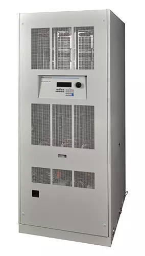
California Instruments - RS Series (90k-540kVA)
High power AC and DC Power Source
Product Overview
The RS Series consists of multiple high power AC and DC power systems that provide controlled AC and DC output for ATE and product test applications.
This high power AC and DC test system covers a wide spectrum of AC and DC power applications at an affordable cost. Using state-of-the-art PWM switching techniques, the RS series combines compactness, robustness and functionality in a compact floor-standing chassis, no larger than a typical office copying machine. This higher power density has been accomplished without the need to resort to elaborate cooling schemes or additional installation wiring. Simply roll the RS unit to its designated location (using included casters), plug it in, and the RS series is ready to work for you.
Simple Operation
The RS Series can be operated completely from its menu driven front panel controller. A backlit LCD display shows menus, setup data, and read-back measurements. IEEE-488, RS232C, USB and LAN remote control interfaces and instrument drivers for popular ATE programming environments are available. This allows the RS Series to be easily integrated into an automated test system. For advanced test applications, the programmable controller version offers full arbitrary waveform generation, time and frequency domain measurements, and voltage and current waveform capture.
Configurations
The RS90 delivers output up to 90kVA in AC mode and 65% of rated power in DC and AC+DC mode. For higher power requirements, the RS180, RS270, RS360, RS450 and RS540 models are available. Available reconfigurable RS models (-MB designation) provide multiple controllers which allow separation of the high power system into up to six individual RS90 units for use in separate applications. This ability to reconfigure the system provides an even greater level of flexibility not commonly found in power systems.
Product Evaluation and Test
Increasingly, manufacturers of high power equipment and appliances are required to fully evaluate and test their products over a wide range of input line conditions. The built-in output transient generation and read-back measurement capability of the RS Series offers the convenience of a powerful, and easy to use, integrated test system.
Regenerative, bidirectional “Green” Power Solution
The RS Series features the ability to both source and sink current, i.e. bi-directional current flow. The RS amplifier is designed to reverse the phase relationship between the AC input
Programming sink (-SNK) mode operation.
Application Software
Windows® application software is included. This software provides easy access to the power source's capabilities without the need to develop any custom code. The following functions are available through this GUI program:
- Steady state output control (all parameters)
- Create, run, save, reload and print transient programs
- Generate and save harmonic waveforms.
- Generate and save arbitrary waveforms.
- Measure and log standard measurements
- Capture and display output voltage and current waveforms.
- Measure, display, print and log harmonic voltage and current measurements.
- Display IEEE-488, RS232C, USB and LAN bus traffic to and from the AC Source to help you develop your own test programs.
Features And Benefits
Key Features
- High Power AC and DC Power Source
Programmable AC and DC power for frequency conversion and product test applications - Expandable Power Levels
Available output power of 90 kVA per unit and multi-unit configurations for power requirements up to 540 kVA and above - Arbitrary & Harmonic Waveform Generation
User defined voltage waveform and distortion programming - Regenerative, bidirectional "Green" Power Solution
Automatic crossover between Source and Current Sink power mode offers regenerative capabilities. Regenerate up to 100% of the rated output power back to the utility grid during sink mode operation. (-SNK option) - Remote Control
Standard RS232C & USB along with optional IEEE-488 & LAN Interfaces are available for automated test applications
規格說明
| Operating Modes | ||
| RS90 | AC, DC, and AC + DC | |
| AC Mode Output | ||
| Frequency | Range : 16.00 - 819.0 Hz, - LF Option : 16.00 - 500.0 Hz, - HF Option : 16.00 - 905 Hz ( supplemental specifications apply above 819 Hz ). Resolution : 0.01 Hz : 16.00 - 81.91 Hz, 0.1 Hz : 82.0 Hz - 819.1 Hz, 1 Hz : 820-905 Hz, SNK 16 - 500Hz | |
| Phase Outputs | 3 Phase, Neutral Floating, Coupling DC ( except - HV Opition and - XU ) | |
| Total Power | RS90 : 90kVA, RS180 : 180kVA, RS270 : 270kVA, RS360 : 360kVA, RS450 : 450kVA, RS540 : 540kVA. Please consult factor for power levels above 540kVA | |
| Load Power Factor | 0 to unity at full output current | |
| AC Mode Voltage | |||||
| Voltage Ranges | Range | V Low | V High | ||
| AC | 0 - 150 V | 0 - 300 V | Load Reg | < 0.25% FS DC to 100 Hz, < 0.5% FS 100 Hz to 819 Hz | |
| AC + DC | 0 - 150 V | 0 - 300 V | Line Reg | < 0.1% FS for 10% line change | |
| External Sense | Voltage drop compensation (5% Full Scale) | ||||
| Harmonic Distortion (Linear) | Less than 0.5% from 16 - 66 Hz, Less than 1% from 66 - 500 Hz, Less than 1.25% above 500 Hz | ||||
| DC Offset | < 20 mV | ||||
| Load Regulation | 0.25% FS @ DC - 100 Hz, 0.5% FS > 100 Hz | ||||
| External Amplitude Modulation | Depth : 0 - 10%, Frequency: DC - 2 KHz | ||||
| Voltage slew rate | 200 µs for 10% to 90% of full scale change into resistive load, 0.5V / µSec | ||||
| AC Mode Current | |||||||
| Steady State AC Current @ Full Scale Voltage Output | Model | RS90 | RS180 | RS270 | RS360 | RS450 | RS540 |
| V Low | 200A | 400A | 600A | 800A | 1000A | 1200A | |
| V High | 100A Per Phase | 200A Per Phase | 300A Per Phase | 400A Per Phase | 500A Per Phase | 600A Per Phase | |
| Note : Constant power mode provides increased current at reduced voltage. See chart below for power up to 125% of Full Scale Current Output at reduced voltages. | |||||||
| Peak Repetitive AC Current | Up to 3.6 x rms current at full scale voltage | ||||||
| Programming Accuracy | Voltage ( rms ) : ± 0.3 Vrms, Frequency : ± 0.01 % of programmed value, Current Limit : - 0 % to + 5 % of programmed value + 1A, Phase : < 0.5° + 0.2° / 100 Hz with balanced load | ||||||
| Programming Resolution | Voltage ( rms ) : 100 mV, Frequency : 0.01 Hz from 16 - 81.91 Hz, 0.1 Hz from 82.0 - 819 Hz, Current Limit: 0.1 A, 3 phase mode, 1.0 A, 1 phase mode, Phase: 0.1° | ||||||
| Constant Power AC Mode - Available Max. AC Current |
|
|
| AC Mode Current | |||||||
| Steady State AC Current @ FS V | |||||||
| Parameter | Frequency | RMS Voltage | RMS Current | Peak Current | VA Power | Real Power | Power Factor ( >0.2kVA ) |
| Range | 16.00 - 820.0Hz | 0 - 400V | 0 - 300A | 0 - 800 Amps | 0–90 KVA | 0–90 KW | 0.00 - 1.00 |
| Accuracy* (±) | 0.01% + 0.01Hz | 0.05V + 0.02%, < 100Hz 0.1V + .02%, 100 - 820Hz | 0.5A + 0.2%, < 100Hz 0.5A + 0.5%, 100 - 500Hz 0.5A + 1.0%, > 500Hz | 0.5A + 0.2%, < 100Hz 0.5A + 0.5%, 100 - 500Hz 0.5A + 1.0%, > 500Hz | 90VA + 0.2%, < 100Hz 90VA + 0.5%, 100 - 500Hz 90VA + 1.0%, > 500Hz | 90W + 0.2%, < 100Hz 90W + 0.5%, 100 - 500Hz 90W + 1.0%, > 500Hz | 0.01, < 100Hz 0.02, 100 - 820Hz |
| Resolution* | 0.01 to 81.91Hz 0.1 to 500Hz 1Hz above 500Hz | 0.01V | 0.01A | 0.01A | 10VA | 10W | 0.01 |
| Note : Constant power mode provides increased current at reduced voltage. See chart below | |||||||
| Measurements - Harmonics | |||||||
| Parameter | Range | Accuracy* (±) | Resolution | ||||
| Frequency Fundamental | 16.00 - 820 Hz | 0.03% + 0.03 Hz | 0.01 Hz | ||||
| Frequency harmonics | |||||||
| RS90 RS180 RS270 RS360 RS450 RS540 | |||||||
| 32.00 Hz – 16 KHz | 0.03% + 0.03 Hz | 0.01 Hz | |||||
| RS90-3Pi | |||||||
| 32.00 Hz – 48 KHz | 0.03% + 0.03 Hz | 0.01 Hz | |||||
| Phase | 0.0 - 360.0° | 2° typ. | 0.5° | ||||
| Voltage | Fundamental | 0.75V | 0.01V | ||||
| Harmonic 2 - 50 | 0.75V + 0.3% + 0.3%/kHz 0.01V | ||||||
| Current | Fundamental | 0.5A | 0.1A | ||||
| Harmonic 2 - 50 | 0.15A + 0.3% + 0.3%/kH 0.1A | ||||||
| Note: For current measurements, specifications apply from 2% to 100% of measurement range. | |||||||
| DC Mode Output | |||||||
| Power | Maximum DC Power at full scale of DC voltage range. RS90 : 45kW, RS180 : 90kW, RS270 : 135kW, RS360: 180kW, RS450 : 225kW, RS540: 270kW | ||||||
| Voltage Ranges | Range: Low (0 - 200 V), High (0 - 400 V) | ||||||
| Output Accuracy | ± 1 Vdc | ||||||
| Load Regulation | < 0.25 % FS | ||||||
| Line Regulation | < 0.1% FS or 10 % line change | ||||||
| Ripple | < 2 Vrms Lo Range, < 3 Vrms Hi Range | ||||||
| DC Mode AC+DC Mode | Model | RS90 | RS180 | RS270 | RS360 | RS450 | RS540 |
| V Low | 100A | 200A | 300A | 400A | 500A | 600A | |
| V High | 50A | 100A | 150A | 200A | 250A | 300A | |
| Per Phase | Per Phase | Per Phase | Per Phase | Per Phase | Per Phase | ||
| Note : Constant power mode provides increased current at reduced voltage. See chart above | |||||||
| Current Limit | Programmable from 0 A to max. current for selected range | ||||||
| AC+DC Mode Output | |
| Output Power | Maximum current and power in AC+DC mode is same as DC mode |
| Protection | |
| Over Load | Remote shutdown, External Sync, Clock / Lock |
| Outputs | Function Strobe / Trigger out, Clock / Lock |
| System Interface | |
| Inputs | Remote shutdown, External Sync, Clock / Lock |
| Outputs | Function Strobe / Trigger out, Clock / Lock |
| Remote Control | |
| IEEE-488 Interface | IEEE-488 (GPIB) talker listener. Subset: AH1, C0, DC1, DT1, L3, PP0, RL2, SH1, SR1, T6, IEEE-488.2 SCPI Syntax |
| RS232C Interface | 9 pin D-shell connector (Supplied with RS232C cable) |
| LAN ( option ) | Ethernet Interface: 10BaseT, 100BaseT, RJ45 |
| USB | Version : USB 1.1; Speed: 460 Kb/s maximum |
| Output Relay | Push button controlled or bus controlled output relay |
| Waveforms | |
| Waveform Types | Sine, Square, Clipped sine, User defined |
| User defined waveform storage | Four groups of 50 user defined arbitrary waveforms of 1024 points for a total of 200. One group can be active at a time |
| AC Input | |||||||
| Voltage | Must be specified at time of order. All inputs are L-L, 3ø, 3 wire + Gnd. 208 ± 10% VAC, 230 ± 10% VAC, 400 ± 10% VAC, 480 ± 10% VAC | ||||||
| Line Voltage ( 3 phase, 3 wire + ground (PE) ) | 208 VLL ±10%, 230 VLL ±10%, 400 VLL ±10%, 480 VLL ±10% | ||||||
| Line VA | RS90 | RS180 | RS270 | RS360 | RS450 | RS540 | |
| 106 KVA | 212 KVA | 318 KVA | 424 KVA | 530 KVA | 636 KVA | ||
| 350 ARMS @ 187 VLL | Each RS90 chassis requires its own AC service. | ||||||
| 314 ARMS @ 207 VLL | Total Line currents are 2 x RS90 | Total Line currents are 3 x RS90 | Total Line currents are 4 x RS90 | Total Line currents are 5 x RS90 | Total Line currents are 6 x RS90 | ||
| 180 ARMS @ 360 VLL | |||||||
| 150 ARMS @ 432 VLL | |||||||
| Line Frequency | 47 - 63 Hz | ||||||
| Efficiency | 85% ( typical ) depending on line and load | ||||||
| Power Factor | 0.95 ( typical ) / 0.99 at full power. | ||||||
| Inrush Current | RS90 | RS180 | RS270 | RS360 | RS450 | RS540 | |
| 460 Apk @ 208 VLL | Each RS90 chassis requires its own AC service. Total Line currents are 2 x RS90 | Each RS90 chassis requires its own AC service. Total Line currents are 3 x RS90 | Each RS90 chassis requires its own AC service. Total Line currents are 3 x RS90 | Each RS90 chassis requires its own AC service. Total Line currents are 5 x RS90 | Each RS90 chassis requires its own AC service. Total Line currents are 6 x RS90 | ||
| 440 Apk @ 230 VLL | |||||||
| 264 Apk @ 400 VLL | |||||||
| 220 Apk @ 480 VLL | |||||||
| Hold - Up Time | > 10ms | ||||||
| Isolation Voltage | 2200 VAC input to output, 1350 VAC input to chassis | ||||||
| AC Service | |
| Inputs / Outputs | Rear Panel Access |
| Regulatory | IEC61010, EN50081 - 2, EN50082 - 2, CE EMC and Safety Mark requirements |
| EMI | CISPR 11, Group1 , Class A |
| Connectors | AC Input and Output terminal blocks behind rear panel access cover. IEEE - 488 ( GPIB ) connector behind rear panel access cover. 9 pin D - Shell RS232C connector*, behind rear panel access cover. Remote voltage sense terminal block behind rear panel access cover. System Interface Connector, DB - 37 behind rear panel access cover. *RS232 DB9 to DB9 cable supplied |
| Physical Dimensions | |
| RS90 Dimensions | Height : 74.5" ( 1892.3 mm ) , Width : 30.3" ( 769.6mm ), Depth : 38.3" ( 972.8mm ), |
| RS90 Weight | Net : 2150 lbs / 975 Kg approximately, Shipping : 2450 lbs / 1111 Kg approximately |
| Chassis | RS90 : Casters and forklift openings |
| Vibration and Shock | Designed to meet NSTA project 1A transportation levels. Units are shipped in wooden crate with forklift slots |
| Air Intake / Exhaust | Forced air cooling, front air intake, rear exhaust |
| Operating Humidity | 0 to 95% RAH, non condensing |
| Temperature | Operating : 0 - 35* ( 30*C max is CP mode ), Storage -20 to + 85*C |
| -MB Option | ||||
| Model | AC Output Power | Phase Outputs | AC / DC Voltage Range | Controller |
| RS180-3Pi-MB | 180kVA | 3 | 150/200 & 300/400 | 2 x RS90 |
| RS270-3Pi-MB | 270kVA | 3 | 150/200 & 300/400 | 3 x RS90 |
| RS360-3Pi-MB | 360kVA | 3 | 150/200 & 300/400 | 4 x RS90 |
| RS450-3Pi-MB | 450kVA | 3 | 150/200 & 300/400 | 5 x RS90 |
| RS540-3Pi-MB | 540kVA | 2 | 150/200 & 300/400 | 6 x RS90 |
| Reconfigurable systems can be separated into stand-alone RS90-3Pi models or combined for higher power levels. | ||||
| Steady State AC RMS Current in Regeneration Mode ( -SNK Option ) | |||||||
| Model | RS90 | RS180 | RS270 | RS360 | RS450 | RS540 | |
| AC Mode | V Lo | 200A | 400A | 600A | 800A | 1000A | 1200A |
| V Hi | 100A | 200A | 300A | 400A | 500A | 600A | |
| per phase | per phase | per phase | per phase | per phase | per phase | ||
| Storage | |
| Non Volatile Mem. storage | 16 instrument setups, 200 user defined waveforms [ Pi only ] |
| Unit Protection | |
| Input Over current | In-line fast acting fuses. Circuit breaker for LV supply. |
| Input Over voltage | Automatic shutdown. |
| Input Over voltage Transients | Surge protection to withstand EN50082 - 1 ( IEC 801-4, 5 ) levels. |
| Output Over current | Adjustable level constant current mode with programmable set point. |
| Output Short Circuit | Peak and RMS current limit. |
| Over temperature | Automatic shutdown |
| System Specification | |
| External Modulation | 0 to 10% |
| Synchronization Input | Isolated TTL input for external frequency control. |
| Trigger Input | External trigger source input. |
| Trigger Output | 400 μs pulse for voltage or frequency change Isolated TTL output Output reverts to Function strobe frequency change. Isolated TTL output. Output reverts to Function strobe when not uses as Trig Out. This function is mutually exclusive with the Function Strobe output. |
| Function Strobe | Active for any voltage or frequency program change. 400 μs pulse for voltage or frequency change. |
| Output Status | Monitors status of output relay. SELV Isolated TTL output. |
| Specs subject to change without notice. | |