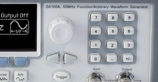
G5100A
PICOTEST 50MHz函數/任意波形產生器
產品說明


G5100A (50MHz 任意波型產生器)
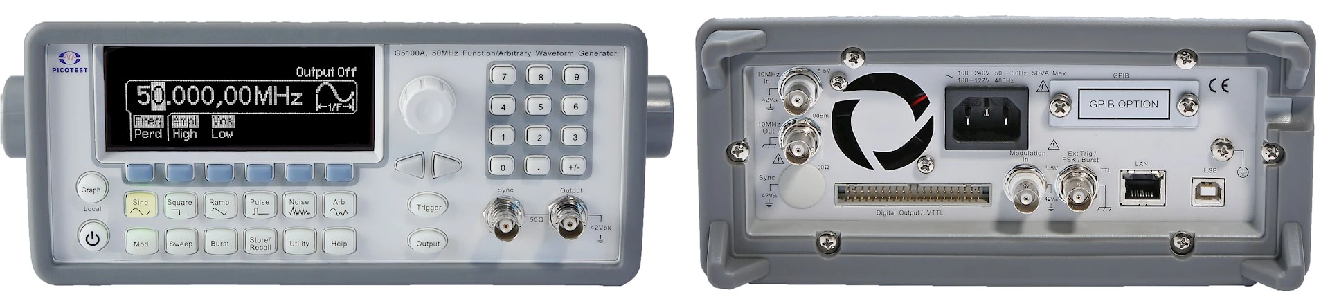
儀鼎儀器 G5100A 50MHz 任意波形產生器採用DDS (Direct Digital Synthesis) 技術,可輸出準確、穩定且無雜訊的低失真正弦波訊號。另外,G5100A還能以上升/下降時間低於10ns, 頻率高達25MHz的方波,以及最高200KHz的線性鋸齒波來滿足使用者使用上的需求。
G5100A可以產生最高10MHz的可調邊緣時間脈波。也由於G5100A提供了可調的週期、脈寬與振幅,因此在需要彈性脈衝訊號的應用上是相當適合的。
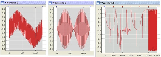
G5100A具備了14位元的解析度以及125 MSa/s的取樣率,並彈性地提供使用者所需波形。它也可以讓使用者儲存最多五筆波形,其中四筆 (4 x 256 K Points)在永久記憶體中、一筆在暫存記憶體中。
儀鼎自創的波形編輯軟體 Wavepat可讓使用者輕易的產生、編輯及下載複雜的波形,而且本軟體亦可以接收並編輯來自安捷倫示波器MSO8104 的波形。
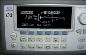
5100A的圖形顯示模式可以讓使用者搭配軟鍵操作信號設定時,以視覺驗證各項設定。
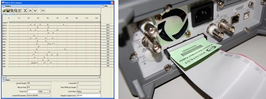
使用者可以透過附加在波形編輯軟體中的 Wavepatt® 功能編輯16位元資料,並可將該資料儲存下來。然後,再根據使用者應用上的需求,透過後置面板上的 Pattern Out 端口將資料傳輸出去。
The front-panel operation of G5100A is simple and user friendly. Users can enter all functions with a single key or two, and use knob or numeric keypad to adjust frequency, amplitude, offset and other parameters. Otherwise, users can also directly input voltage values in Vpp, Vrms, dBm or high & low levels. Timing parameters can be entered in Hertz (Hz) or second.
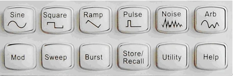
Users can easily use the following functions.
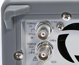
The G5100A external frequency reference allows users synchronizing to an external 10 MHz clock, to another G5100A, or any other unit which can support 10-MHz-frequency-input function。
| G5100A | |||
| USB | LAN | GPIB | |
| Function Change | 27.0 | 27.0 | 27.0 |
| Frequency Change | 1.3 | 1.6 | 1.3 |
| Amplitude Change | 18.5 | 17.7 | 18.2 |
| Select Builtln Arb | 9.8 | 8.0 | 6.8 |
| Select User Arb | USB | LAN | GPIB |
| 256K Arb | 68.0 | 70.4 | 68.2 |
| 64K Arb | 26.0 | 23.8 | 21.8 |
| 16K Arb | 14.6 | 12.2 | 10.2 |
| 4K Arb | 19.0 | 16.6 | 14.6 |
| G5100A | |||
| Binary transfer | USBFS | *LAN | GPIB |
| 256K Arb | 1,420.0 | 1,357.0 | 924.0 |
| 64K Arb | 347.0 | 359.0 | 236.0 |
| 16K Arb | 80.0 | 107.1 | 57.6 |
| 4K Arb | 21.8 | 58.2 | 15.0 |
| Display | Graph mode for visual verification of signal settings | |
| Capability | Standard waveforms | Sine,Square,Ramp,Triangle,Pulse,Noise,DC |
| Built-in arbitray waveforms | Exponential Rise and Fall,Negative ramp,Sin(x)/x,Cardiac | |
| WAVEFORM CHARACTERISTIC | ||
| Sine | Frequency | 1 μHz to 50 MHz |
| Amplitude Flatness[1][2] ( Relative to 1KHz ) |
0.1dB ( <100KHz ) | |
| 0.15dB ( <5MHz ) | ||
| 0.3dB ( <20MHz ) | ||
| 0.5dB ( <50MHz ) | ||
| Harmonic distortion[2][2] ( unit : dBc ) |
DC to 20 KHz -70 ( <1Vpp ) -70 ( ≥1Vpp ) |
|
| 20 KHz to 100 KHz -65 ( <1Vpp ) -60 ( ≥1Vpp ) |
||
| 100 kHz to 1 MHz -50 ( <1Vpp ) -45 ( ≥1Vpp ) |
||
| 1 MHz to 20 MHz -40 ( <1Vpp ) -35 ( ≥1Vpp ) |
||
| 20 MHz to 50 MHz -35 ( <1Vpp ) -30 ( ≥1Vpp ) |
||
| Total Harmonic distortion[2][2] | DC to 20 KHz, Output ≥0.5 Vpp THD+N ≤ 0.06% |
|
| Spurious[2][4] (non-harmonic) |
DC to 1 MHz -70 dBC |
|
| 1 MHz to 50 MHz | ||
| -70 dBc + 6 dB / octave | ||
| Phase Noies ( 10K Offset ) |
-155 / dBC / Hz , typical when f ≥ 1MHz, V ≥ 0.1 Vpp |
|
| Square | Frequency | 1 μHz to 25 MHz |
| Rise / Fall time | < 10 ns | |
| Overshoot | < 2 % | |
| Variable Duty Cycle | 20% to 80% ( to 10 MHz ) | |
| 40% to 60% ( to 25 MHz ) | ||
| Asymmetry | 1% of period + 5 ns ( @ 50% duty ) |
|
| Jitter ( RMS ) | 200 ps when f ≥ 1MHz, V ≥ 0.1 Vpp |
|
| Ramp, Triangle | Frequency | 1 μHz to 200 MHz |
| Linearity | < 0.1% of peak output | |
| Symmetry | 0.0% ~ 100.0% | |
| Pulse | Frequency | 500 μHz to 10 MHz |
| Pulse width | 20 ns minimum | |
| 10 ns res. ( period ≤ 10s ) | ||
| Variable Edge Time | < 10 ns to 100 ns | |
| Overshoot | < 2% | |
| Jitter ( RMS ) | 200 ps when f ≥ 50kHz, V ≥ 0.1 Vpp |
|
| Noise | Bandwidth | 20 MHz typical |
| Arbitrary | Frequency | 1 μHz to 10 MHz |
| Length | 2 to 256 K | |
| Resolution | 14 bits ( including sign ) | |
| Sample Rate | 125 MSa/s | |
| Min Rise / Fall Time |
30ns typical | |
| Linearity | < 0.1% of peak output | |
| Settling Time | <250ns to 0.5% of final value | |
| Jitter ( RMS ) | 6ns +30ppm | |
| Non-volatile Memory |
4 waveforms * 256K Points | |
| COMMON CHARACTERISTIC | ||
| Frequency | Resolution | 1 μHz |
| Amplitude | Range | 10mVpp to 10Vpp in 50Ω |
| 20mVpp to 20Vpp in Hi-Z | ||
| Accuracy[1][2] ( at 1KHz ) |
±1% of setting ± 1mVpp | |
| Units | Vpp, Vrms, dBm | |
| Resolution | 4 digits | |
| DC Offset | Range ( Peak AC + DC ) |
±5V in 50Ω |
| ±10V in Hi-Z | ||
| Accuracy[1][2] | ±2% of offset setting ±0.5% of amplitude setting |
|
| Resolution | 4 digits | |
| Main Output | Impedance | 50 Ω typical |
| Isolation | 42 Vpk maximum to earth | |
| Protection | short-clrcuit protected; overload automatically disables main output |
|
| Internal Frequency reference Accuracy[5] | ±10ppm in 90 days | |
| ±20ppm in 1 year | ||
| External Frequency reference |
Standard / Option | Standard |
| External Frequency Input | Lock Range | 10 MHz ± 500 Hz |
| Level | 100mVpp ~ 5Vpp | |
| Impedance | 1 KΩ typical, AC coupled | |
| Lock Time | < 2 Sec | |
| External | Lock Range | 10 MHz |
| Frequency Output | Level | 632mVpp ( OdBm ) , typical |
| Impedance50 | 50Ω typical , AC coupled | |
| Phase Offset | Range | -360° to +360° |
| Resolution | 0.0001° | |
| Accuracy | 8ns | |
| Modulation | ||
| Modulation Type | AM, FM, PM, FSK, PWM, Sweep and Burst | |
| AM | Carrier | Sine, Square, Ramp, Arb |
| Source | Internal / external | |
| Intermal Modulation | Sine, Square, Ramp, Triangle, Noise, Arb | |
| Frequency ( Internal ) | 2mHz to 20KHz | |
| Depth | 0.0% ~ 120.0% | |
| FM | Carrier | Sine, Square, Ramp, Arb |
| Source | Internal / external | |
| Intermal Modulation | Sine, Square, Ramp, Triangle, Noise, Arb | |
| Frequency ( Internal ) | 2mHz to 20KHz | |
| Deviation | DC ~ 25MHz | |
| PM | Carrier | Sine, Square, Ramp, Arb |
| Source | Internal / external | |
| Intermal Modulation | Sine, Square, Ramp, Triangle, Noise, Arb | |
| Frequency ( Internal ) | 2mHz to 20KHz | |
| Deviation | 0.0° to 360° | |
| PWM | Carrier | Pulse |
| Source | Internal / external | |
| Intermal Modulation | Sine, Square, Ramp, Triangle, Noise, Arb | |
| Frequency ( Internal ) | 2mHz to 20KHz | |
| Deviation | 0% ~ 100% of pulse width | |
| FSK | Carrier | Sine, Square, Ramp, Arb |
| Source | Internal / external | |
| Intermal Modulation | 50% duty cycle Square | |
| Frequency ( Internal ) | 2mHz to 100KHz | |
| External Modulation Input[6] |
Voltage Range | ±5V full scale |
| Input Resistance | 8.7KΩ typical | |
| Bandwidth | DC to 20KHz | |
| SWEEP | Waveforms | Sine, Square, Ramp, Arb |
| Type | Linear or logarithmic | |
| Direction | up or down | |
| Sweep Time | 1 ms ~500 Sec | |
| Trigger | Internal, External or Manual | |
| Marker | falling edge of sync signal ( programmable frequency ) |
|
| BURST[7] | Waveforms | Sine, Square, Ramp, Triangle, Noise, Arb |
| Type | Counted ( 1 to 50000 cycles ), Infinite, Gated | |
| Start / Stop Phase | -360° to +360° | |
| Internal Period | 1 uS ~ 500 Sec | |
| Gated Source | External trigger | |
| Trigger Source | Internal, External or Manual | |
| Trigger Input | Level | TTL compatible |
| Slope | Rising or Falling ( Selectable ) | |
| Pulse width | > 100 ns | |
| Impedance | >10KΩ , DC coupled | |
| Latency | < 500 ns | |
| Trigger Output | Level | TTL compatible into ≥ 1 KΩ |
| Pluse width | > 400 ns | |
| Output Impedance | 50 Ω typical | |
| Maximum rate | 1 MHz | |
| Fan-out | ≤ 4 Picotest G5100As | |
| Patterm Mode CHARCTERISTIC | ||
| Clock | Maximum rate | 50 MHz |
| Output | Level | TTL compatible into ≥ 2 KΩ |
| Output Impedance | 110 Ω typical | |
| Clock | Output Impedance | 110 Ω typical |
| General | ||
| Power Supply | CAT II 110 - 240V AC ±10% | |
| Power Cord Freq. | 50 Hz to 60 Hz | |
| Power Consumption | 50VA max | |
| Operating Environment | 0°C to 55°C | |
| Storage Temperature | -30°C to 70°C | |
| Interface | ( Standard ) USB, LAN, ( Optional ) GPIB | |
| Language | SCPI-1993, IEEE-488.2 | |
| Dimensions | 107 ( H ) x 224 ( W ) x 380 ( D ) mm | |
| Weight | 4.08 Kg | |
| Safety Designed to | IEC61010-1, EN61010-1, UL61010-1 | |
| EMCTested to | EN61326, IEC61000-3, IEC61000-4 | |
| Warm-up Time | 1 hour | |
| Warranty | 1 Year | |
[1] Add 1/10th of output amplitude and offset spec per °C for operation outside the range of 18°C to 28°C
[2] Autorange enabled
[3] DC offset set to 0V
[4] Spurious output at low amplitude is -75 dBm typical
[5] Add 1 ppm / °C average for operation outside the range of 18°C to 28°C
[6] FSK uses trigger input ( 1 MHz maximum )
[7] Sine and square waveforms above10MHz are allowed only with an "infinite" burst count