
產品介紹
首頁 > 產品介紹 > 交直流電源 > 直流電源供應器
直流電源供應器


功能說明
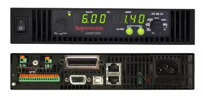
Sorensen XG 850 Watt
Half or full rack programmable DC power supply
for greater accuracy and efficiency
Product Overview
The Sorensen XG Series is an 850 Watt, 1U half-rack DC power supply. The XG Series is the new standard for powerful, programmable DC power systems. Designed for test, production, laboratory, OEM and quality assurance applications, the XG Series provides a wealth of features to ensure accuracy and greater efficiency. It puts clean, reliable power at your disposal and delivers stable, variable output voltage and current for a broad range of development, test and system requirements.
Features And Benefits
◎ Highest Power Density
The Sorensen XG Series is an 850 Watt, 1U half-rack DC power supply. The XG Series is the new standard for powerful, programmable DC power systems. Designed for test, production, laboratory, OEM and quality assurance applications, the XG Series provides a wealth of features to ensure accuracy and greater efficiency. It puts clean, reliable power at your disposal and delivers stable, variable output voltage and current for a broad range of development, test and system requirements.
◎ Comprehensive Digital and Analog Interface Options
The XG Series comes standard with USB 2.0, RS-232, RS-485, isolated and non-isolated analog interfaces to provide a comprehensive set of options to connect to a PC or other network device. This design provides the convenience of being able to accommodate a wide range of installation configurations. Ethernet and GPIB interfaces are available as options.
◎ Scalable, Multi-Unit Design
XG Series power supplies can be connected in parallel or series to produce greater current or voltage output for your applications. This scalability allows you to build rackmounted systems with the XG Series that exactly meet your existing requirements, while allowing for future expansion.
◎ Multi-Channel Support
Up to 30 XGs Series can be connected easily via an RS-485 bus to provide the ultimate flexibility in remote programming. This eliminates the cost and complexity of requiring GPIB cards in each unit. Once connected, multiple power supplies can be controlled via a single LAN, USB 2.0, GPIB, RS-232 or RS-485 interface. This provides an efficient option to centrally manage each XG Series needed for your applications.
◎ Straightforward Front Panel Controls
The XG Series is equipped with a unique push-button encoder and function selector dial to provide a simple, uncluttered front panel. Both voltage and current can be set quickly and easily using these two controls. Front panel access can be locked out to ensure secure remote operation. This streamlined front panel layout results in fast, intuitive set-up and operation of the XG Series.
◎ High Reliability
To guarantee long-term trouble-free performance, the XG Series was designed with reliability in mind. Softswitching technology ensures higher mean time between failure (MTBF) by eliminating high voltage transients found in conventional hard-switching power supplies which can cause premature failure of power components. AMETEK engineers also rigorously tested the XG Series during the design phase using Highly Accelerated Life Testing (HALT). This rigorous test procedure combines powerful thermal and vibration technologies to stress a product beyond its rated specifications. HALT testing allows our engineers to uncover and correct design issues early in the development cycle. This care in design and comprehensive testing ensures the XG Series exceeds the reliability and quality standards of both AMETEK and our customers.
◎ Five-Year Warranty
The XG is backed by a comprehensive five-year warranty, the longest in the market. Our superior design and testing techniques result in highly reliable products that will provide you with years of trouble-free performance.
規格說明
| Output Ratings | |||
| Model | Output Voltage 1 | Output Current 2, 9 | Output Power 3 |
| XG 6-110 | 6 V | 110 A | 670 W |
| XG 8-100 | 8 V | 100 A | 810 W |
| XG 12-70 | 12 V | 70 A | 850 W |
| XG 20-42 | 20 V | 42 A | 850 W |
| XG 33-25 | 33 V | 25 A | 835 W |
| XG 40-21 | 40 V | 21 A | 850 W |
| XG 60-14 | 60 V | 14 A | 850 W |
| XG 80-10.5 | 80 V | 10.5 A | 850 W |
| XG 100-8.5 | 100 V | 8.5 A | 860 W |
| XG 150-5.6 | 150 V | 5.6 A | 850 W |
| XG 300-2.8 | 300 V | 2.8 A | 850 W |
| XG 600-1.4 | 600 V | 1.4 A | 850 W |
| Line Regulation | |||
| Model | Voltage ( 0.005% of rated output voltage +2 mV ) 4 |
Current ( 0.01% of rated output current +1 mA ) 5 |
|
| XG 6-110 | 2.3 mV | 13 mA | |
| XG 8-100 | 2.4 mV | 12 mA | |
| XG 12-70 | 2.6 mV | 9 mA | |
| XG 20-42 | 3.0 mV | 6.2 mA | |
| XG 33-25 | 3.7 mV | 4.5 mA | |
| XG 40-21 | 4 mV | 4.1 mA | |
| XG 60-14 | 5 mV | 3.4 mA | |
| XG 80-10.5 | 6 mV | 3.1 mA | |
| XG 100-8.5 | 7 mV | 2.9 mA | |
| XG 150-5.6 | 9.5 mV | 2.6 mA | |
| XG 300-2.8 | 17 mV | 2.3 mA | |
| XG 600-1.4 | 32 mV | 2.1 mA | |
| Load Regulation | |||
| Model | Voltage ( 0.005% of rated output voltage + 2 mV ) 6 |
Current ( 0.02% of rated output current +4 mA ) 7 |
|
| XG 6-110 | 2.3 mV | 27 mA | |
| XG 8-100 | 2.4 mV | 25 mA | |
| XG 12-70 | 2.6 mV | 19 mA | |
| XG 20-42 | 3.0 mV | 13.4 mA | |
| XG 33-25 | 3.7 mV | 10 mA | |
| XG 40-21 | 4 mV | 9.2 mA | |
| XG 60-14 | 5 mV | 7.8 mA | |
| XG 80-10.5 | 6 mV | 7.1 mA | |
| XG 100-8.5 | 7 mV | 6.7 mA | |
| XG 150-5.6 | 9.5 mV | 6.1 mA | |
| XG 300-2.8 | 17 mV | 5.6 mA | |
| XG 600-1.4 | 32 mV | 5.3 mA | |
| Output Ratings | |||
| Model | Output Noise ( rms, 300 kHz ) | Output Ripple ( p-p, 20 MHz ) |
|
| Voltage | Current 8 | Voltage | |
| XG 6-110 | 8 mV | 200 mA | 50 mV |
| XG 8-100 | 8 mV | 180 mA | 50 mV |
| XG 12-70 | 8 mV | 120 mA | 50 mV |
| XG 20-42 | 8 mV | 75 mA | 50 mV |
| XG 33-25 | 8 mV | 60 mA | 50 mV |
| XG 40-21 | 8 mV | 45 mA | 50 mV |
| XG 60-14 | 8 mV | 35 mA | 50 mV |
| XG 80-10.5 | 8 mV | 25 mA | 80 mV |
| XG 100-8.5 | 8 mV | 20 mA | 80 mV |
| XG 150-5.6 | 10 mV | 16 mA | 100 mV |
| XG 300-2.8 | 25 mV | 10 mA | 150 mV |
| XG 600-1.4 | 50 mV | 6 mA | 250 mV |
|
1. Maximum output voltage is guaranteed to be ≤ 0.2% of the rated voltage at zero output setting, using the front panel or digital remote programming modes. Note: All specifications are subject to change. |
|||
| Output Ratings | |||
| Model | Maximum Recommended Remote Sense Line Drop Compensation per Line10 | Up-prog. Response Time, 0~Vmax 11 | Efficiency (100/200 VAC input) 12 |
| XG 6-110 | 1 V | 60 ms | 75/77% |
| XG 8-100 | 1 V | 60 ms | 77/80% |
| XG 12-70 | 1 V | 60 ms | 79.5/82.5% |
| XG 20-42 | 1.5 V | 60 ms | 82/85% |
| XG 33-25 | 2 V | 60 ms | 83/86% |
| XG 40-21 | 2 V | 60 ms | 83/87% |
| XG 60-14 | 3 V | 60 ms | 83/87% |
| XG 80-10.5 | 5 V | 100 ms | 83/87% |
| XG 100-8.5 | 5 V | 100 ms | 83/87% |
| XG 150-5.6 | 5 V | 100 ms | 83/87% |
| XG 300-2.8 | 5 V | 150 ms | 83/87% |
| XG 600-1.4 | 5 V | 250 ms | 83/87% |
| Output Ratings | |||
| Model | Down-prog. Response Time: Full Load | Down-prog. Response Time: No Load | Over-Voltage Trip Point |
| XG 6-110 | 50 ms | 300 ms | 0.5–7.5 V |
| XG 8-100 | 50 ms | 400 ms | 0.5–10 V |
| XG 12-70 | 50 ms | 500 ms | 1–15 V |
| XG 20-42 | 50 ms | 600 ms | 1–24 V |
| XG 33-25 | 50 ms | 700 ms | 2–39 V |
| XG 40-21 | 50 ms | 800 ms | 2–44 V |
| XG 60-14 | 50 ms | 900 ms | 3–66 V |
| XG 80-10.5 | 80 ms | 1000 ms | 3–95 V |
| XG 100-8.5 | 100 ms | 1200 ms | 3–125 V |
| XG 150-5.6 | 150 ms | 1800 ms | 3–180 V |
| XG 300-2.8 | 150 ms | 2200 ms | 5–330 V |
| XG 600-1.4 | 250 ms | 3500 ms | 5–660 V |
| Regulatory Approvals | |
| Safety |
CSA 22.2 No. 61010-1, 60950-1-07 and UL61010-1, UL60950-1-(2nd Ed).19 Marked with cCSAus, CE for EMC & low voltage directive |
| EMC | Complies with EN61326-1 Complies with EN55022, Class B, FCC Part 15B for conducted emissions Complies with EN55022, Class A, FCC Part 15A for radiated emissions Complies with EN61000-4 series of standards for immunity |
|
9. When using remote sense, the total of the load voltage and the load line drops must not exceed the rated output of the power supply. For example, for an XG 6-110 in an application with 1 V of Applies to all footnotes: Programming and Readback: RS-232, RS-485, USB built in. GPIB, Ethernet optional. Specifications are guaranteed from 1% to 100% of the rated output voltage, current, and power. Note: All specifications are subject to change. |
|
| Environmental Specifications (Indoor use) | |
| Operating Temperature Range | 32°F to 122°F, 100% load ( 0°C to 50°C ) |
| Storage Temperature Range | -4°F to 158°F ( –20° C to 70°C ) |
| Operating Humidity Range | 30–90% RH ( no condensation ) |
| Storage Humidity Range | 10–95% RH ( no condensation ) |
| Operating Altitude | Up to 6,500 feet ( 2,000 m ) |
| Installation Category | II ( IEC 1010-1 ) |
| Pollution Degree | 2 ( IEC 1010-1 ) |
| Output Performance Specifications | |
| Temperature Coefficient | 100 PPM /°C from rated output voltage, after a 30-minute warm-up |
| Drift (8 hours) | 0.05% of rated output voltage & current over an 8 hour interval with constant line, load & temperature, after a 30-minute warm-up |
| Hold-up Time | Typical 20 ms at any rated input line. |
| Transient Response Time2 | Less than 1 ms for 6 V to 60 V models. Less than 2 ms for 80 V to 600 V models |
| Meter Accuracy | 0.5% ± 1 count |
| Aux Output 1 | +5V: +0.4V, – 0.5V at 0.4A +15V: +1.2V, – 1.4V at 0.4A |
| Isolation 4 | 1500Vac or 2121Vdc between mains terminals and accessible conductive parts / chassis ground. Output to chassis 18 500Vac. |
|
1. Current: 0.51 A minimum guaranteed, 0.72 A typically available. Overcurrent protection (each output) is automatic, non-latching. When OCP is tripped the aux voltage folds back and will recover to nominal condition |
|