
產品介紹
首頁 > 產品介紹 > 交直流電源 > 直流電源供應器
直流電源供應器


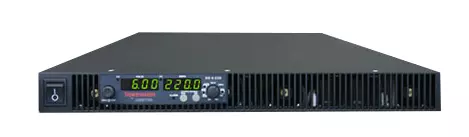
 1U programmable DC power supply | 洛克Lockinc")
功能說明
Sorensen XG 1700 Watt
1700 Watt, 1U programmable DC power supply
with constant voltage and constant current modes
Product Overview
The XG 1700 is an industry leading programmable DC power supply designed for test, production, laboratory, OEM and quality assurance applications. The XG 1700 is a 1700 Watt, 1U programmable power supply with constant voltage and constant current modes, automatic cross-over and numerous features enabling cost effective, easy integration.
Features And Benefits
◎ Easy Integration
XG 1700 has many control and indication signals such as shutdown, constant voltage (CV) vs. constant current (CC) mode indication, OVP, OCP, OTP, and so on. In addition, the logical-high or -low is free selectable. Thus enabling the XG 1700 to replace existing power supplies with little or no system engineering required.
◎ Free Selectable Analog Control Range
Most DC power supplies provide a 0 to 5 or 0 to 10 V analog control range to control the DC output from zero to full DC output range. With the XG 1700, the analog control range is free selectable starting at 0V to an upper range between 2V and 10V. In other words, the analog programming interface range is freely adjustable.
◎ Auxiliary DC Output Channels with Control
In many ATE systems one or more low power, fixed voltage supplies are needed to provide electrical power for any periphery within the ATE cabinet. For this purpose, the XG 1700 provides two standard auxiliary DC output channels. Both auxiliary power channels are controllable directly from the front-panel or through SCPI commands. With these channels, it is possible to drive outputdisconnect or polarity-reversal relays, without needing a complicated computer controlled relay board.
◎ DC-Waveforms Through Internal Sequencing
To allow for extremely fast programming, sequences can be programmed into and stored in memory using standard SCPI commands through USB, RS-232/485, LXI or GPIB.
◎ Variable Fan Speed COntrol
The XG 1700’s innovative approach to fan speed is determined by internal heat sink temperature. This allows the fans to adjust to a constant optimal speed when the output of the supply is being pulsed. This also reduces noise and increases fan life.
◎ Power Saving Standby Mode
When the XG 1700 has been in an idle state, the supply can go into “sleep mode”, much like a computer monitor. This will allow the user to save energy and minimize lab noise. Since an XG 1700 left in sleep mode is still “on” the user will have quicker access to an enabled output.
◎ Output Auto Start Mode (Auto Restart)
The Auto Start mode establishes the state of the output of the power supply after recovery from a complete power cycle (all front panel LEDs are not illuminated), or after recovery from a PC failure or reboot. If Auto Start mode is set to On, the power supply output will return to its previous value. Also, after the loss of any remote digital control, the XG unit will remain active in its last programmed setting and will not disrupt any test process.
◎ Auxiliary Auto Start Mode
The Auxiliary Auto Start mode determines the state of the auxiliary output after a complete power cycle (all front panel LEDS are not illuminated). With Auxiliary Auto Start mode turned to On, the auxiliary output will be activated after the power supply is powered up again.
◎ Foldback Mode
Foldback mode is used to disable the output when a transition is made between the operating modes. The power supply will turn off/disable the output and lock in foldback mode after a specified delay if the power supply transitions into CV mode or into CC mode, depending on the foldback mode settings. This feature is particularly useful for protecting current or voltage sensitive loads. Foldback can be set to trigger a switch when transitioning from CV to CC mode or from CC to CV mode.
規格說明
| Output Ratings1 | |||
| Model | Output Voltage1 | Output Current2 | Output Power3 |
| XG 6-220 | 6 V | 220 A | 1330 W |
| XG 8-200 | 8 V | 200 A | 1610 W |
| XG 12-140 | 12 V | 140 A | 1690 W |
| XG 20-84 | 20 V | 84 A | 1690 W |
| XG 33-50 | 33 V | 50 A | 1690 W |
| XG 40-42 | 40 V | 42 A | 1690 W |
| XG 60-28 | 60 V | 28 A | 1690 W |
| XG 80-21 | 80 V | 21 A | 1690 W |
| XG 100-17 | 100 V | 17 A | 1710 W |
| XG 150-11.2 | 150 V | 11.2 A | 1690 W |
| XG 300-5.6 | 300 V | 5.6 A | 1690 W |
| XG 600-2.8 | 600 V | 2.8 A | 1690 W |
| Line Regulation | ||
| Model | Voltage( 0.005% of rated output voltage +2 mV )4 | Current ( 0.01% of rated output current +2 mA )5 |
| XG 6-220 | 2.3 mV | 24 mA |
| XG 8-200 | 2.4 mV | 22 mA |
| XG 12-140 | 2.6 mV | 16 mA |
| XG 20-84 | 3.0 mV | 10.4 mA |
| XG 33-50 | 3.7 mV | 7 mA |
| XG 40-42 | 4 mV | 6.2 mA |
| XG 60-28 | 5 mV | 4.8 mA |
| XG 80-21 | 6 mV | 4.1 mA |
| XG 100-17 | 7 mV | 3.7 mA |
| XG 150-11.2 | 9.5 mV | 3.12 mA |
| XG 300-5.6 | 17 mV | 2.56 mA |
| XG 600-2.8 | 32 mV | 2.28 mA |
| Load Regulation | ||
| Model | Voltage ( 0.005% of rated output voltage + 2 mV )6 | Current ( 0.02% of rated output current +5 mA )7 |
| XG 6-220 | 2.3 mV | 49 mA |
| XG 8-200 | 2.4 mV | 45 mA |
| XG 12-140 | 2.6 mV | 33 mA |
| XG 20-84 | 3.0 mV | 22 mA |
| XG 33-50 | 3.7 mV | 15 mA |
| XG 40-42 | 4 mV | 13 mA |
| XG 60-28 | 5 mV | 1.06 mA |
| XG 80-21 | 6 mV | 9.21 mA |
| XG 100-17 | 7 mV | 8.4 mA |
| XG 150-11.2 | 9.5 mV | 7.2 mA |
| XG 300-5.6 | 32 mV | 6.1 mA |
| XG 600-2.8 | 9.5 mV | 5.6 mA |
| Output Ratings | |||
| Model | Output Noise (rms, 300 kHz) | Output Ripple (p-p, 20 MHz) | |
| Voltage | Current8 | Voltage | |
| XG 6-220 | 8 mV | 400 mA | 50 mV |
| XG 8-200 | 8 mV | 340 mA | 50 mV |
| XG 12-140 | 8 mV | 240 mA | 50 mV |
| XG 20-84 | 8 mV | 150 mA | 50 mV |
| XG 33-50 | 8 mV | 120 mA | 50 mV |
| XG 40-42 | 8 mV | 90 mA | 50 mV |
| XG 60-28 | 8 mV | 70 mA | 50 mV |
| XG 80-21 | 8 mV | 50 mA | 80 mV |
| XG 100-17 | 8 mV | 40 mA | 80 mV |
| XG 150-11.2 | 10 mV | 32 mA | 100 mV |
| XG 300-5.6 | 25 mV | 20 mA | 150 mV |
| XG 600-2.8 | 50 mV | 12 mA | 250 mV |
| 1. Maximum output voltage is guaranteed to be ≤ 0.2% of the rated voltage at zero output setting, using the front panel or digital remote programming modes. 2. Maximum output current is guaranteed to be ≤ 0.4% of the rated current at zero output setting, using the front panel or digital remote programming modes, and when measured with rated load resistance. 3. Total output power is also based on AUX1 Output Voltage ( 5 V ) and AUX1 Output Current ( 0.5 A ) and AUX2 Output Voltage ( 15 V ) and AUX2 Output Current ( 0.5 A ). 4. From 85 - 132 Vac or 170 - 265 Vac, constant load. 5. From 85 - 132 Vac or 170 - 265 Vac, constant load. 6. From no load to full load, constant input voltage. 7. For load voltage change, equal to the unit voltage rating, constant input voltage. 8. For 6 V models the current ripple is measured at 2 - 6 V output voltage and full output current. For all other models, the current ripple is measured at 10 - 100% output voltage and full output current. Note: All specifications are subject to change. |
|||
| Output Ratings | |||
| Model | Maximum Recommended Remote Sense Line Drop Compensation per Line 9 | Up-prog. Response Time, 0~Vmax 10 | Efficiency (100/200 VAC input)11 |
| XG 6-220 | 1 V | 60 ms | 75/77% |
| XG 8-200 | 1 V | 60 ms | 77/78% |
| XG 12-140 | 1 V | 60 ms | 80/83% |
| XG 20-84 | 1.5 V | 60 ms | 82/85% |
| XG 33-50 | 2 V | 60 ms | 83/86% |
| XG 40-42 | 2 V | 60 ms | 83/87% |
| XG 60-28 | 3 V | 60 ms | 83/87% |
| XG 80-21 | 5 V | 100 ms | 83/87% |
| XG 100-17 | 5 V | 100 ms | 83/87% |
| XG 150-11.2 | 5 V | 100 ms | 83/87% |
| XG 300-5.6 | 5 V | 150 ms | 83/87% |
| XG 600-2.8 | 5 V | 250 ms | 83/87% |
| Output Ratings | |||
| Model | Down-prog. Response Time: Full Load | Down-prog. Response Time: No Load | Over-Voltage Trip Point |
| XG 6-220 | 50 ms | 300 ms | 0.5–7.5 V |
| XG 8-200 | 50 ms | 400 ms | 0.5–10 V |
| XG 12-140 | 50 ms | 500 ms | 1–15 V |
| XG 20-84 | 50 ms | 600 ms | 1–24 V |
| XG 33-50 | 50 ms | 700 ms | 2–39 V |
| XG 40-42 | 50 ms | 800 ms | 2–44 V |
| XG 60-28 | 50 ms | 900 ms | 3–66 V |
| XG 80-21 | 80 ms | 1000 ms | 3–95 V |
| XG 100-17 | 100 ms | 1200 ms | 3–125 V |
| XG 150-11.2 | 150 ms | 1800 ms | 3–180 V |
| XG 300-5.6 | 150 ms | 2200 ms | 5–330 V |
| XG 600-2.8 | 250 ms | 3500 ms | 5–660 V |
| 9. When using remote sense, the total of the load voltage and the load line drops must not exceed the rated output of the power supply. For example, for an XG 6 - 220 in an application with 1 V of load line loss ( 0.5 V / Line ), the maximum available load voltage would be 6-1= 5 V. Note: The unit may operate at higher output voltages than this, but there is no guarantee That the power supply will meet performance specifications. Ultimately, the upper limit of the output voltage will be determined by internal circuitry of the power supply ( non-adjustable ) 10. With rated, resistive load. 11. At 100 / 200 Vac input voltage and maximum output power. Applies to all footnotes: Programming and Readback: RS-232, RS-485, USB built in. GP1B, Ethernet optional. Specifications are guaranteed from 1% to 100% of the rated output voltage, current, and power. * Typical Note: All specifications are subject to change. |
|||
| AC Line Input Specifications | |
| Rated AC Input Voltage / Frequency |
100 - 240 Vac, 47 - 63 Hz |
| Operational AC Input Voltage / Frequency | 85 - 265 Vac continuous, 47 - 63 Hz, single phase |
| Input Current ( at 100 / 200 Vac ) |
23 / 12 A |
| Inrush Current ( 100 / 200 Vac ) |
Less than : 50 A |
| Power Factor Correction | 0.99@100 / 200 Vac, rated output power |
| Programming Mode | |||
| APG | ISOL | DIGITAL | |
| Voltage & Current Output Voltage Programming | 0 - 100% 2~up to 10 V, programmable | ||
| Voltage & Current Output Resistive Programming | 0 - 100% 2~up to 10 kΩ, programmable | ||
| Voltage Output Resistor Programming | 0 - 100% 2~up to 10 kΩ, programmable | ||
| Output Voltage and Current Monitor | 0-100% 2~up to 10 V, programmable | ||
| Voltage Programming Accuracy ( mV )1 | ± 0.5% of rated output voltage, max ( 0 - 4V / 4K range ) |
± 0.1% of rated output voltage | |
| Current Programming Accuracy ( mV )1 | ± 1% of rated output current, max ( 0 - 4V / 4K range ) |
± 0.2% of rated output current | |
| Voltage Readback Accuracy ( mV ) | ± 1% of rated output voltage | ± 0.1% of rated output voltage | |
| Current Readback Accuracy ( mV ) | ± 1% of rated output current | ± 0.2% of rated output current | |
| Isolation ( Prog and Readback Lines ) | With respect to chassis potential : 500 V | With respect to : chassis potential : 600 V negative or positive main output 1500 V negative or positive auxiliary output 300 V |
|
| Voltage and Current Programming Resolution | 0.012% of full scale | ||
| Voltage and Current Readback Resolution | |||
| Parallel Operation | Up to 4 units in master / slave | Up to 4 units in master / slave | Up to 4 units in master / slave |
| Series Operation | Up to 2 units ( with external diodes ) |
Up to 2 units
( with external diodes ) |
|
| Constant Voltage ( CV ) Constant Current ( CC ) Indicator | CV : TTL High (4-5 V) CC TTL Low ( 0-0.6 V ) |
||
| Shutdown Control 2 | Logic low 0.0 - 1.4 V Logic high 2.0 - 15 V Dry contact compatible |
||
| AUX On / Off Control | TTL level or dry contact compatible | ||
| Power Supply Status Signal |
TTL high : OK ( 4-5 V )
TTL low : fail ( 0-0.6 V )
|
||
| Interlock Enable / Disable | Dry contact. Open/Short: On or Off programmable | ||
| 1. Typical APG or isolated APG accuracy can be improved to max accuracy by user calibration at the specific range selected 2. The shutdown input has user selectable negative logic operation via front panel or remote digital input/output Note: All specifications are subject to change. |
|||
| Output Performance Specifications | |
| Temperature Coefficient | 100 PPM / °C from rated output voltage, after a 30-minute warm-up* |
| Drift ( 8 hours ) | 0.05% of rated output voltage & current over an 8 hour interval with constant line, load & temperature, after a 30-minute warm-up |
| Hold-up Time | Typical 20 ms at any rated input line. |
| Transient Response Time 1 | Less than 1 ms for 6 V to 60 V models. Less than 2 ms for 80 V to 600 V models* |
| Meter Accuracy | 0.5% ± 1 count |
| Aux output 3 | +5 V : +0.4 V, – 0.5 V at 0.4 A +15 V : +1.2 V, – 1.4 V at 0.4 A |
| Isolation 2 | 1500Vac or 2121Vdc between mains terminals and accessible conductive parts / chassis ground. Output to chassis 500Vac. |
| Environmental Specifications (Indoor use) | |
| Operating Temperature Range | 32 °F to 122 °F, 100% load ( 0 °C to 50 °C ) |
| Storage Temperature Range | -4°F to 158°F ( -20 °C to 70 °C ) |
| Operating Humidity Range | 30 - 90% RH ( no condensation ) |
| Storage Humidity Range | 10 - 95% RH ( no condensation ) |
| Operating Altitude | Up to 6,500 feet ( 2,000 m ) |
| Installation Category | II ( IEC 1010-1 ) |
| Pollution Degree | 2 ( IEC 1010-1 ) |
| Mechanical Specifications | |
| XG 1700 Watt ( W×H×D ) |
16.8 x 1.7 x 19.0 inch ( 429 x 43.6 x 483 mm without rack mount ears ) |
| Weight | 22 lb ( 10 kg ) |
| Cooling | Forced air cooling by internal fans |
| Regulatory Approvals | |
| Safety | CSA 22.2 No. 61010-1, 60950-1-07 and UL61010-1, UL60950-1- ( 2nd Ed ) 12 12. Marked with cCSAus, CE for EMC & low voltage directive |
| EMC | Complies with EN61326-1 Complies with EN55022, Class B, FCC Part 15B for conducted emissions Complies with EN55022, Class A, FCC Part 15A for radiated emissions Complies with EN61000-4 series of standards for immunity |
| * Typical 1. Time for the output voltage to recover within 0.05% at its rated output for a load change 10-90% of rated ouput current. Output set point 10-100% 2. Double insulation on primary to secondary isolation barriers. Basic insulation primary to protective earth ground. 3. Current : 0.51 A minimum guaranteed, 0.72 A typically available. Overcurrent protection (each output) is automatic, non-latching. When OCP is tripped the aux voltage folds back and will recover to nominal condition when the over current condition is removed ( typ. <0.2A ). To protect external circuits attached to the aux outputs it is recommended that customers use an appropriately rated fuse in series with the aux outputs set point 10-100% Note : All specifications are subject to change. |
|