J2200A
J2120A- (NEW) Picotest Optocoupler CTR Measurement Kit
產品說明


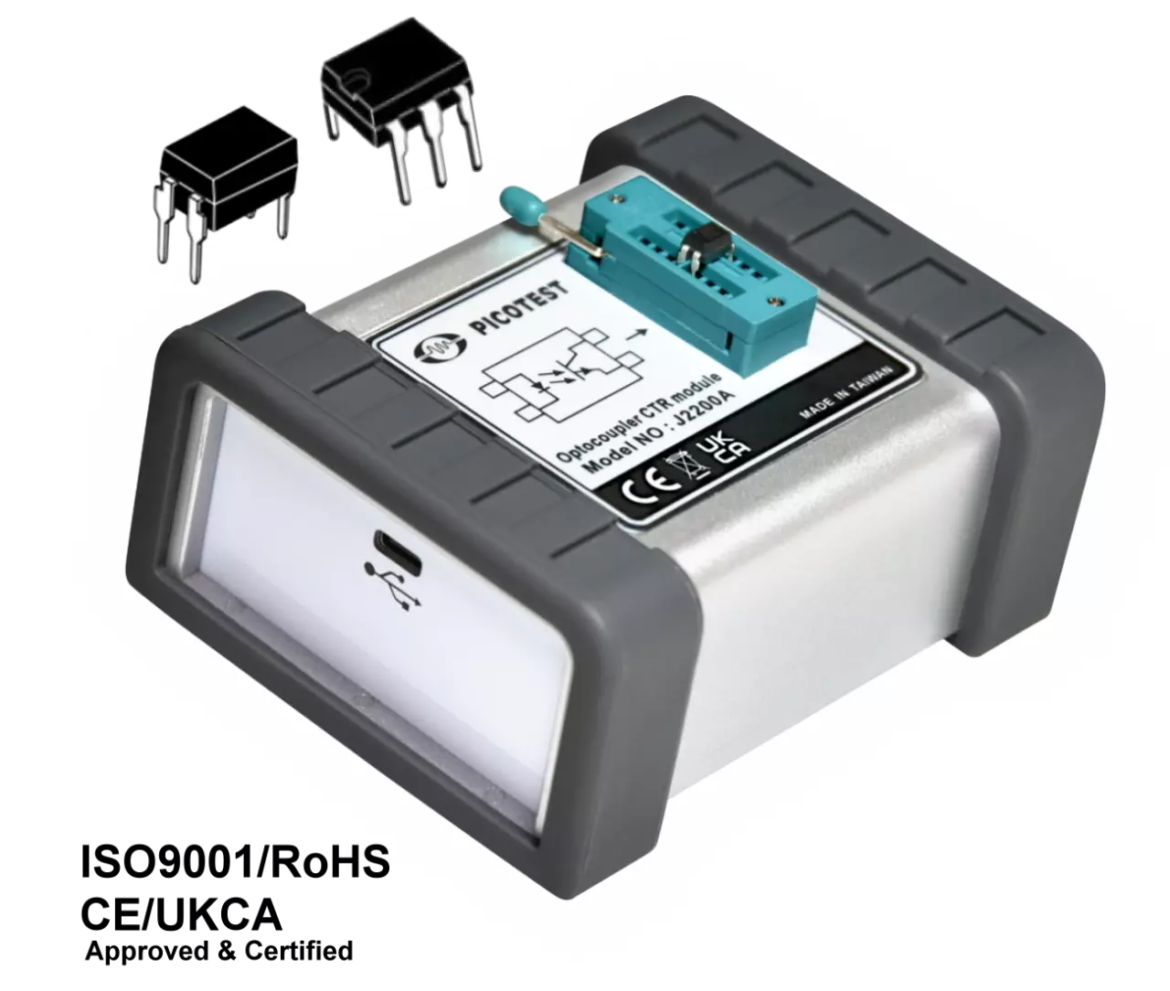
An optocoupler is an electronic component that allows electrical signals to be transferred between two circuits without a direct electrical connection. It consists of a light emitting diode ( LED ) that is optically coupled to a photodetector, such as a phototransistor or a photodiode.
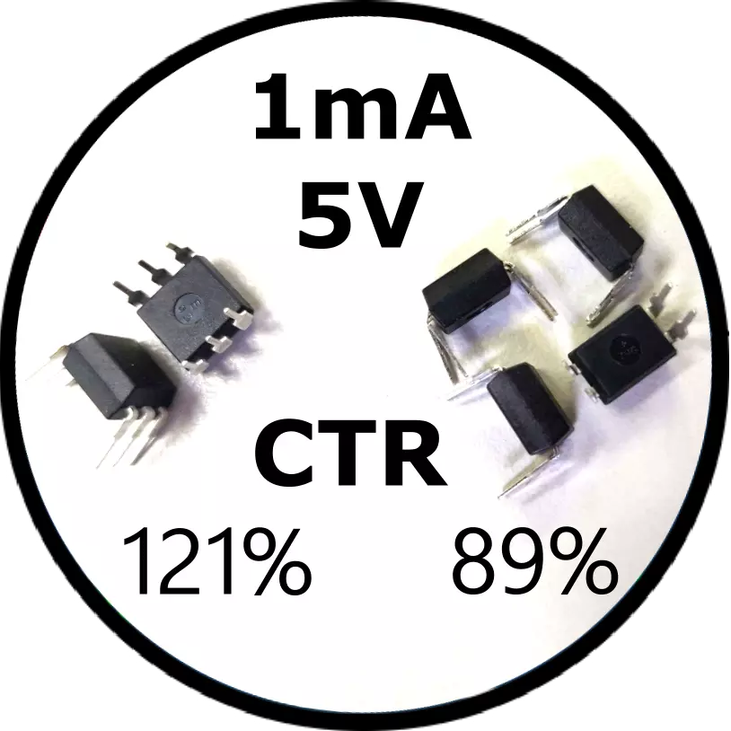
optocouplers come in different types, and the CTR (current transfer ratio) rank is also varied, ranging from 50% to 600%. In addition, the manufacturer's specifications do not provide AC parameters such as △CTR and △Rd, which are necessary for designing isolation feedback control circuits.
To address this issue, the J2200A is an essential tool for engineers in designing isolation feedback control circuits. It provides both AC and DC parameters of various bias voltages, making it easier for engineers to select and design the appropriate optocoupler for their circuit. However, this testing process may not be a one--time task since the optocoupler selection varies depending on the application, and engineers may need to test different optocouplers to find the most suitable one for their circuit design. The range of CTR specifications for optocouplers is also quite wide, varying from 50%~600% in some cases. Precision circuit applications may not be able to tolerance this deviation, especially since the nominal CTR is not defined.
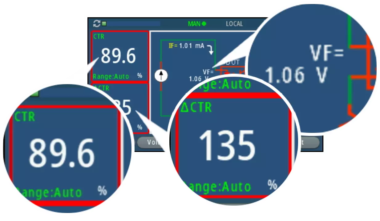
The J2200A optocoupler test instrument provides various bias conditions for optocouplers and greatly eases the measurement of key parameters, including CTR. The J2200A provides pulse current mode measurement function, which reduces the temperature rise during the testing process improving the accuracy of the measurement.
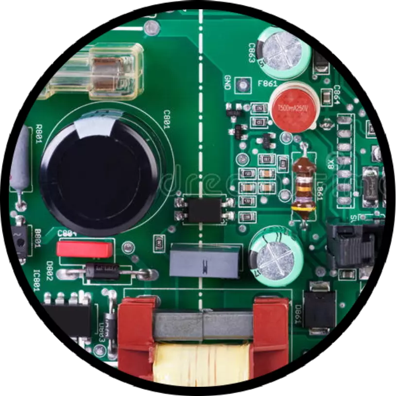
Optocoupler procurement is often exempted from incoming component inspection, but given counterfeit products are appearing in the market, optocoupler inspection has become more necessary. The J2200A is a very convenient tool for IQC.
Engineers can quickly and easily assess performance characteristics, such as isolated power circuit design,with the J2200A plug and play capabilities.
This is a significant improvement over the past, when building an expensive test station and spending a lot of time tuning CTR values was necessary.
Using the J2200A to inspect opto-couplers allows you to easily identify any parts that are fake or out-of-specification, even for large quantities of parts.
Effectively categorizing opto-couplers into groups using the J2200A will significantly aid in subsequent work.
For example, the faster you can obtain CTR valuse, the more efficient the design process will be.
| USAGE 1 - Used as A Circuit Design Tool |
USAGE 2 - Used as An IQC Tester |
USAGE 3 - Used as A CTR Ranking Classifier |
 |
 |
 |
| 1. Output Rating - Continue IF Mode | |
| Item | Value |
| VCE ¹ | 15 V ( max ) |
| IF ( @1mA ) | 50 µA ~ 12 mA |
| IF ( @10mA ) | 0.5 mA ~ 12 mA |
| 2. Output Rating - Pulse IF Mode | |
| Item | Value |
| VCE ¹ | 15 V ( max ) |
| IF ( @1mA ) | 50 µA ~ 12 mA |
| IF ( @10mA ) | 0.5 mA ~ 12mA |
| IF ³ ( @100mA ) | 5 mA ~ 60 mA |
| 3. Output Rating - Ic | |
| Item | Value |
| Ic ( @1mA ) | 2.4 mA ( max ) |
| Ic ( @10mA ) | 24 mA ( max ) |
| Ic ³ ( @100mA ) | 72 mA ( max ) |
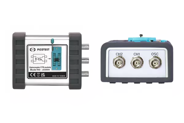
| 4. OSC Port | |
| Item | Value |
| Input Impedance | < 13 dBm |
| Bandwidth | 10 Hz ~ 100 KHz |
| Maximum Input Powe | 10 Hz ~ 100 KHz |
| Modulator Gain ( @1mA ) | 0.45 mA / V |
| Modulator Gain ( @10mA ) | 4.5 mA / V |
| Modulator Gain ( @100mA ) | 45 mA / V |
| 5. CH1, CH2 | |
| Item | Value |
| Output Impedance ³ | 50 ohm |
| Bandwidth | > 100 kHz |
| 6. Programming Accuracy ( Setting + Range ) | |
| Item | % |
| VCE ( Setting + Range ) | 1% + 50 mV |
| IF ( Setting + Range ) | 0.5% + 0.5% |
| 7. Read - Back Accuracy | |||
| Item | % ( Setting + Range ) | Item ( Typical ) | % |
| VCE | 1% + 50 mV | CTR | 2% |
| VF | 1% + 50 mV | △ CTR | 5% |
| Ic | 1% + 50 mV | △ Rd | 10% |
| IF | 0.5% + 0.5% | ||
| 8. General Specifications | |
| Item | Description |
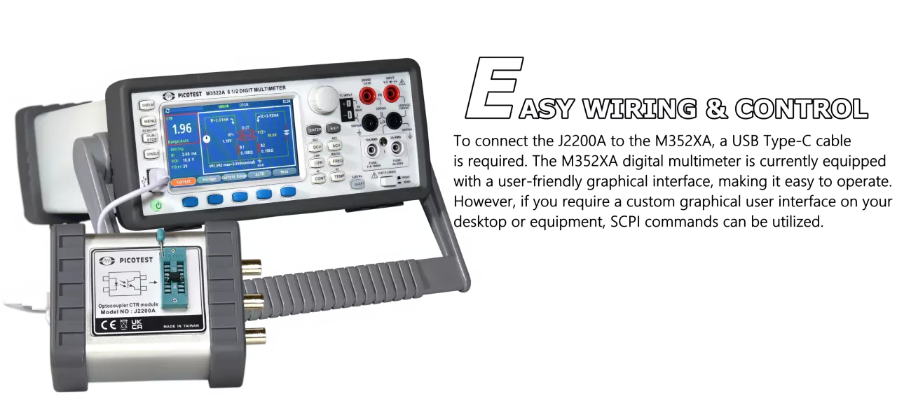
| Input Power Supply | 5 V / 1 A, 5 VA, USB Type-C |
| Operating Temp. | 20°C ~ 40°C |
| Storage Temp. | -30°C ~ 70°C |
| Size / Weight | 123 ( L ) x 89 ( W ) x 55 ( H ) mm / 237 g |
| Certificate | CE Compliant |
| Warranty | 1 - Year |